It is always good practice to verify a circuit before using.
Switching-Mode Power Supplies are the most used circuits nowadays. But there are some difficulties with verifying their circuits: vendors do not publish models for all controllers; a model can be locked to be used with some tool; there may be errors in a model; average models want correct parameters and you need some practice of using them; transient models take a lot of time to get small-signal response and also can have errors.
Let’s try to verify one circuit using my favorite electronics design tool “Circuit Calculator”.
This tool can compute control functions for basic switching-mode power supplies analytically. Of course, they are simplified, but good enough to be used in practice.
Let’s verify a SEPIC converter from LT8582 datasheet, page 36.
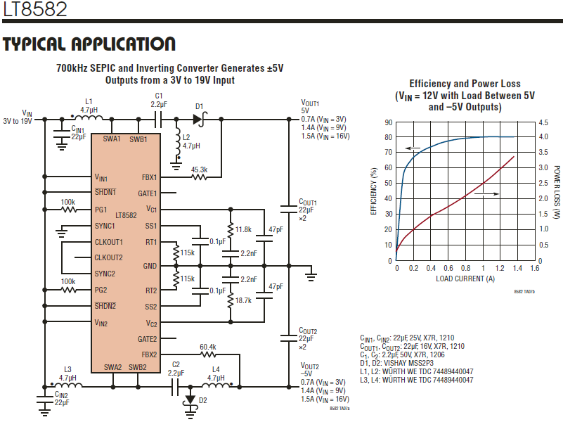
We will start with parameters of the compensation network.
Looking through the datasheet we find the gma parameter of the error amplifier, 270 uA/V, in Table 8, page 29.
Open “Circuit Calculator”, go to “Control Loop”, choose “Compensation, Type II, Transconductance Amplifier” and enter only this parameter. We do not need to change other input fields, because we need reverse engineering.

Then go to “Reverse of Cascade” and enter component values to get circuit parameters.
Look at the circuit and see that there is only one feedback resistor. We need to know another one. A table on page 2 says that “Positive Feedback Voltage “ is 1.204V and “Positive FBX Pin Bias Current” is 83.3 uA, so we can calculate the resistor value:
Rbottom = 1.204 V / 83.3 uA = 14.453 kOhm.

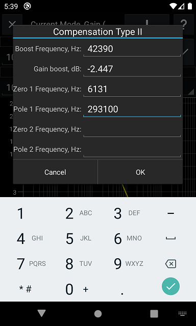
We see that the zero frequency is 6.131 kHz, the pole frequency is 293.1 kHz, the integrator pole is 4.626 kHz and the maximum phase boost is 73.54° at 42.39 kHz.
Ok, we have all information about the compensation network.
Now we go to “Switching-Mode Power Supplies”, choose “Basic SEPIC DC/DC Converter” and enter parameters of the circuits. We want to verify stability, so use the lowest input voltage and the highest output current at this voltage. Since we do not know inductor current ripples used to design this circuit we enter maximum values to get the lowest inductors values and change them later.
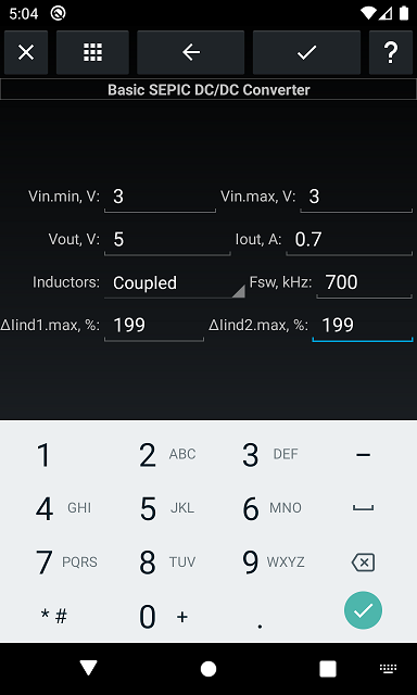

At first we will look at initial values. We see that inductors values are lower than 4.7 uH, so the circuit operates in continuous conduction mode (CCM), the coupling capacitor Cdc is greater than in the circuit, so we need to pay attention on it, and the output capacitor value is twice times lower than in the circuit at 1% output voltage ripple, so the value in the circuit looks correct.
Now we need to adjust component values. Find parameters of the recommended power inductor:
“Inductance — Connected In Parallel” is 4.7 uH
“Inductance — Connected In Series” is 18.8 uH
Open “Tools”, choose “Coupled Inductors”, enter these values and see that we have such values when the coupling coefficient is 1.

Now we return to the converter circuit and enter all components values. After changing inductor values we see that the minimum Cdc value is 1.7 uF, so its value in the circuit is correct.

We see that the maximum switch current is 2.28 A and it matches with LT8582 parameters. The inductor maximum current is 1.43 A that is lower than 1.85 A of the used inductor. Inductor current ripples are 23% and 42% which are good values. Capacitor current ripples are about 1 A, so there is no problem with recommended 1210 capacitors. The recommended diode has a double margin of both current and voltage.
Now it is time to verify stability.
Open the “Charts” window. This is a current mode controller, so we need the gm.ps parameter and slope compensation. Table 8 on page 29 has this parameter, 15.1 A/V, but there is not slope compensation, so we will use 55% because it gives quite high peak at half of the switching frequency. Enter these values and see the control-to-output function.
Press the “Compensation” button and enter the parameters of the compensation network which we got earlier.
Now we see final parameters of the circuit:
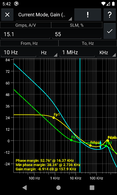
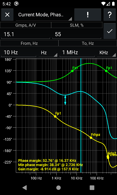
Yellow line is power stage small signal response, green line is compensation network response and cyan line is total response.
We see that the crossover frequency is 16.37 kHz, the phase margin is about 53°, the minimum phase margin is about 38° at 2.7 kHz and the gain margin is about -9 dB.
So, the circuit looks correct and can be used.
OK, we verified a circuit from a datasheet, but are there wrong circuits? Of course!
Let’s verify this circuit, Figure 3 from here.
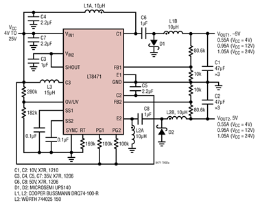
LT8471 datasheet says that the “Positive Feedback Voltage” is 789 mV and the “Negative Feedback Voltage” is -788 mV.
Go to “Power”, open “Vout of DC/DC Converter” and enter 5 V as the output voltage and 789 mV as the reference.
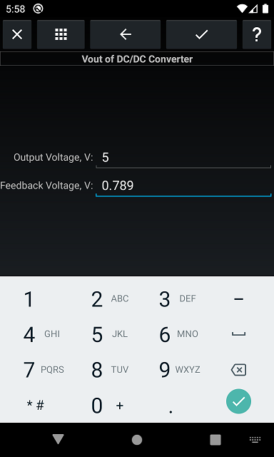
Now enter the bottom resistor value from the circuit, 10 kOhm.

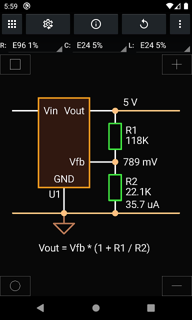
We see that the top resistor value must be 53.6 kOhm and not 80.6 kOhm.
But what output voltage we will have at this circuit?
Go to “Reverse of Cascade” and enter the resistor values from the circuit.
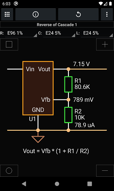
I would not want to send 7 V to my 5 V circuit!
Circuits in the datasheet use 59 kOhm and 316 kOhm for 5 V outputs, so it is an obvious mistake in this circuit.
But we did not verify the output voltage in the first circuit with LT8582. Let’s do this now. The reference voltage is 1.204 V and the top resistor is 45.5 K.

We see that the bottom resistor is 14.3 kOhm that matches with the previously calculated Rbottom value and the output voltage is 5.02 V, so the feedback network is correct.
The final question is: can we trust this tool completely? I do not know.
Electronics is complex, and equations and simplified models can be used with limitations and precautions. And still it helps and saves a lot of time.
Switching-Mode Power Supplies are the most used circuits nowadays. But there are some difficulties with verifying their circuits: vendors do not publish models for all controllers; a model can be locked to be used with some tool; there may be errors in a model; average models want correct parameters and you need some practice of using them; transient models take a lot of time to get small-signal response and also can have errors.
Let’s try to verify one circuit using my favorite electronics design tool “Circuit Calculator”.
This tool can compute control functions for basic switching-mode power supplies analytically. Of course, they are simplified, but good enough to be used in practice.
Let’s verify a SEPIC converter from LT8582 datasheet, page 36.
We will start with parameters of the compensation network.
Looking through the datasheet we find the gma parameter of the error amplifier, 270 uA/V, in Table 8, page 29.
Open “Circuit Calculator”, go to “Control Loop”, choose “Compensation, Type II, Transconductance Amplifier” and enter only this parameter. We do not need to change other input fields, because we need reverse engineering.
Then go to “Reverse of Cascade” and enter component values to get circuit parameters.
Look at the circuit and see that there is only one feedback resistor. We need to know another one. A table on page 2 says that “Positive Feedback Voltage “ is 1.204V and “Positive FBX Pin Bias Current” is 83.3 uA, so we can calculate the resistor value:
Rbottom = 1.204 V / 83.3 uA = 14.453 kOhm.
We see that the zero frequency is 6.131 kHz, the pole frequency is 293.1 kHz, the integrator pole is 4.626 kHz and the maximum phase boost is 73.54° at 42.39 kHz.
Ok, we have all information about the compensation network.
Now we go to “Switching-Mode Power Supplies”, choose “Basic SEPIC DC/DC Converter” and enter parameters of the circuits. We want to verify stability, so use the lowest input voltage and the highest output current at this voltage. Since we do not know inductor current ripples used to design this circuit we enter maximum values to get the lowest inductors values and change them later.
At first we will look at initial values. We see that inductors values are lower than 4.7 uH, so the circuit operates in continuous conduction mode (CCM), the coupling capacitor Cdc is greater than in the circuit, so we need to pay attention on it, and the output capacitor value is twice times lower than in the circuit at 1% output voltage ripple, so the value in the circuit looks correct.
Now we need to adjust component values. Find parameters of the recommended power inductor:
“Inductance — Connected In Parallel” is 4.7 uH
“Inductance — Connected In Series” is 18.8 uH
Open “Tools”, choose “Coupled Inductors”, enter these values and see that we have such values when the coupling coefficient is 1.
Now we return to the converter circuit and enter all components values. After changing inductor values we see that the minimum Cdc value is 1.7 uF, so its value in the circuit is correct.
We see that the maximum switch current is 2.28 A and it matches with LT8582 parameters. The inductor maximum current is 1.43 A that is lower than 1.85 A of the used inductor. Inductor current ripples are 23% and 42% which are good values. Capacitor current ripples are about 1 A, so there is no problem with recommended 1210 capacitors. The recommended diode has a double margin of both current and voltage.
Now it is time to verify stability.
Open the “Charts” window. This is a current mode controller, so we need the gm.ps parameter and slope compensation. Table 8 on page 29 has this parameter, 15.1 A/V, but there is not slope compensation, so we will use 55% because it gives quite high peak at half of the switching frequency. Enter these values and see the control-to-output function.
Press the “Compensation” button and enter the parameters of the compensation network which we got earlier.
Now we see final parameters of the circuit:
Yellow line is power stage small signal response, green line is compensation network response and cyan line is total response.
We see that the crossover frequency is 16.37 kHz, the phase margin is about 53°, the minimum phase margin is about 38° at 2.7 kHz and the gain margin is about -9 dB.
So, the circuit looks correct and can be used.
OK, we verified a circuit from a datasheet, but are there wrong circuits? Of course!
Let’s verify this circuit, Figure 3 from here.
LT8471 datasheet says that the “Positive Feedback Voltage” is 789 mV and the “Negative Feedback Voltage” is -788 mV.
Go to “Power”, open “Vout of DC/DC Converter” and enter 5 V as the output voltage and 789 mV as the reference.
Now enter the bottom resistor value from the circuit, 10 kOhm.
We see that the top resistor value must be 53.6 kOhm and not 80.6 kOhm.
But what output voltage we will have at this circuit?
Go to “Reverse of Cascade” and enter the resistor values from the circuit.
I would not want to send 7 V to my 5 V circuit!
Circuits in the datasheet use 59 kOhm and 316 kOhm for 5 V outputs, so it is an obvious mistake in this circuit.
But we did not verify the output voltage in the first circuit with LT8582. Let’s do this now. The reference voltage is 1.204 V and the top resistor is 45.5 K.
We see that the bottom resistor is 14.3 kOhm that matches with the previously calculated Rbottom value and the output voltage is 5.02 V, so the feedback network is correct.
The final question is: can we trust this tool completely? I do not know.
Electronics is complex, and equations and simplified models can be used with limitations and precautions. And still it helps and saves a lot of time.