
Во время очередной ревизии радиоэлектронного барахла и распихивания по коробочкам мне попался контроллер AVR atxmega256a3u. Дабы развеять скуку было решено сделать некое подобие звуковой карты, а точнее ЦАП, подключаемый к компьютеру. Что из этого получилось смотрите под катом.
Линейка микроконтроллеров XMEGA является развитием знакомых большинству любителей электроники контроллеров MEGA, добавлено много интересных плюшек, но все описанное ниже можно реализовать на традиционной серии. Рекомендую лишь использовать те контроллеры, где побольше ОЗУ.
От слов к разработке, поразмыслив пришел к такой структуре устройства:

Буду воспроизводить музыку из WAV-файлов, моно, 8 бит с частотой дискретизации 44.1 кГц. Посылка последовательного порта состоит из 10 бод (стартовый и стоповый биты, 8 битов данных), значит требуется скорость не ниже 441 кБод/с. Аппаратура позволяет работать быстрее, беру с запасом скорость передачи данных 2000 кБод/с.
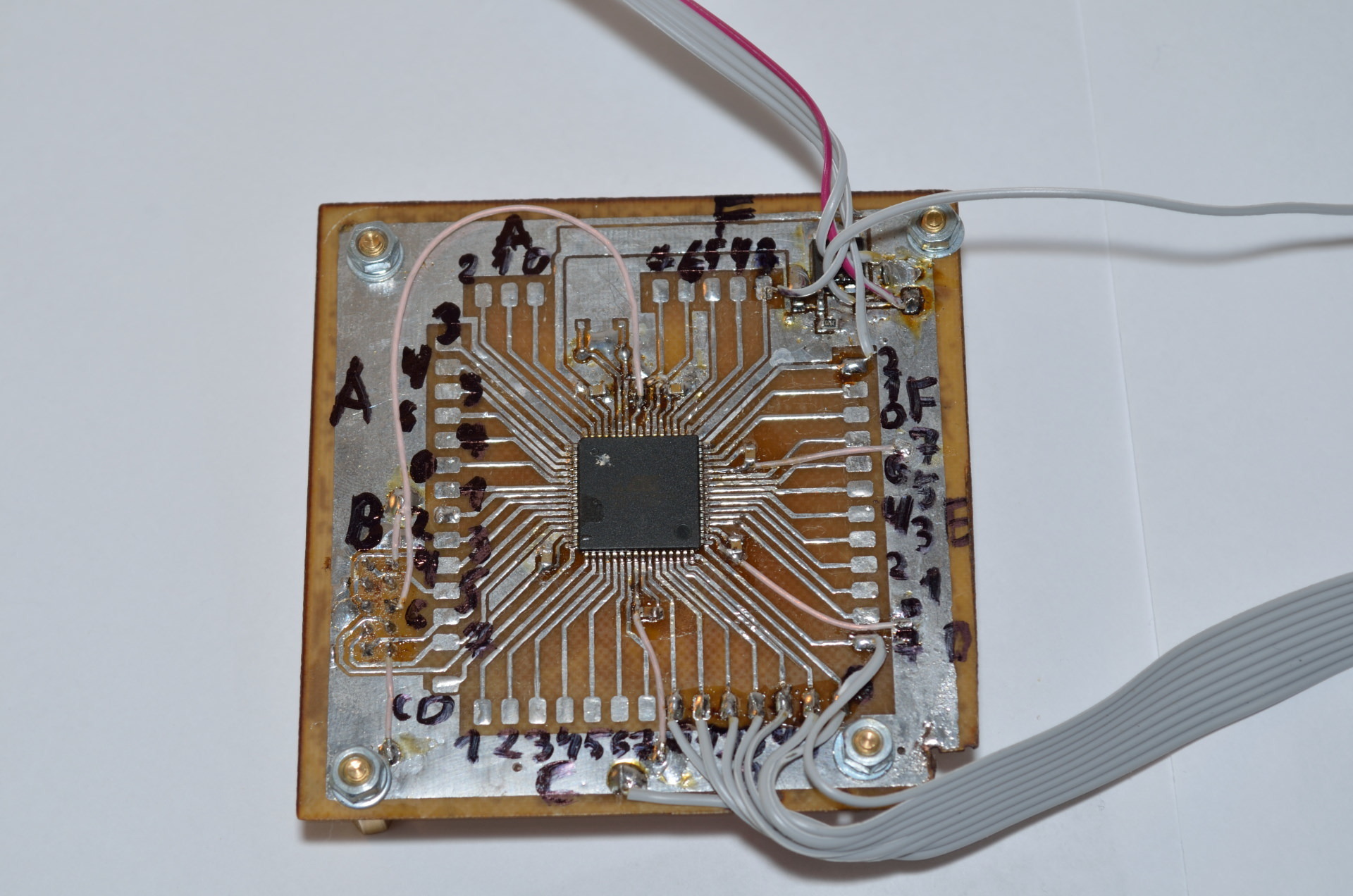
Внутри контроллера буфер FIFO, он же очередь «первый пришел — первый вышел». По таймеру с частотой 44.1 кГц запускается прерывание извлекающее из буфера очередной отсчет и передающее его цифро-аналоговому преобразователю, а также по необходимости выполняется запрос очередного пакета данных у ЭВМ. Размышляя обо всем этом трассирую и травлю «отладочную» плату для микроконтроллера:
Самым интересным в этой разработке пожалуй является ЦАП. В моем микроконтроллере есть встроенный ЦАП, но использовать его не спортивно, к тому же в большинстве микроконтроллеров такой роскоши нет. Ничего страшного, ЦАП можно сделать самому из горсти резисторов по схеме R-2R:
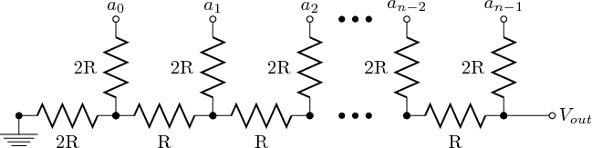
Такая схема позволяет получить на выходе напряжения в диапазоне от 0 В до уровня логической единицы, в моем случае это 3.3 В. Сделаю восьмибитный ЦАП, у меня под рукой лишь резисторы с допустимым отклонением 5%, а значит точность потеряется с пятого разряда поскольку (1/2^5)<0.05. Тем не менее, надеюсь, что младшие разряды позволят озвучить слабые спектральные составляющие сигнала. Собираю из резисторов номиналом 5.1 кОм вот такого монстра:
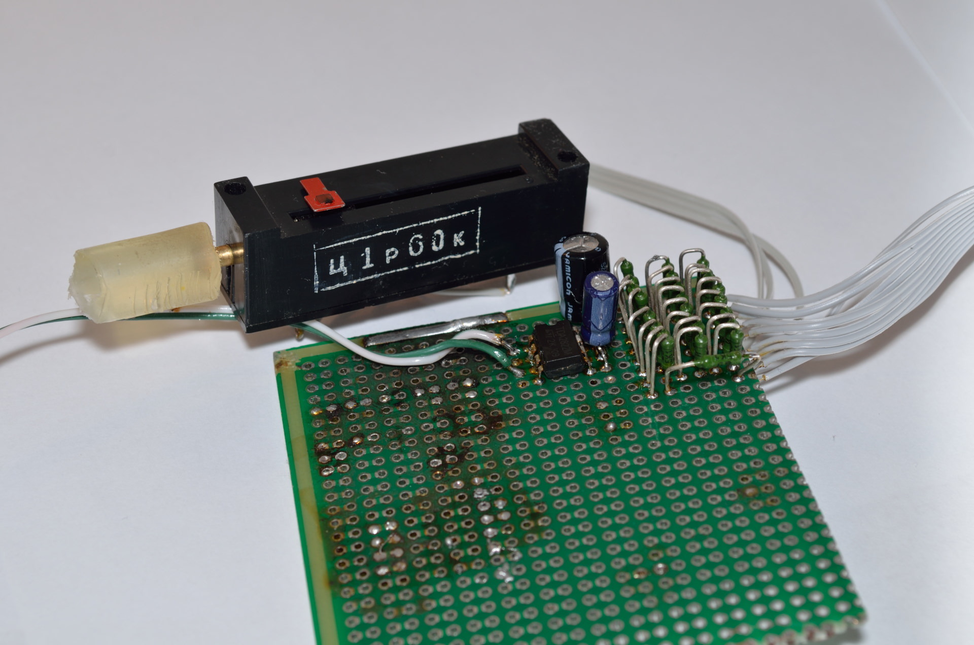
Тут же ставлю усилитель TDA2822M, подключаю по мостовой схеме из даташита:

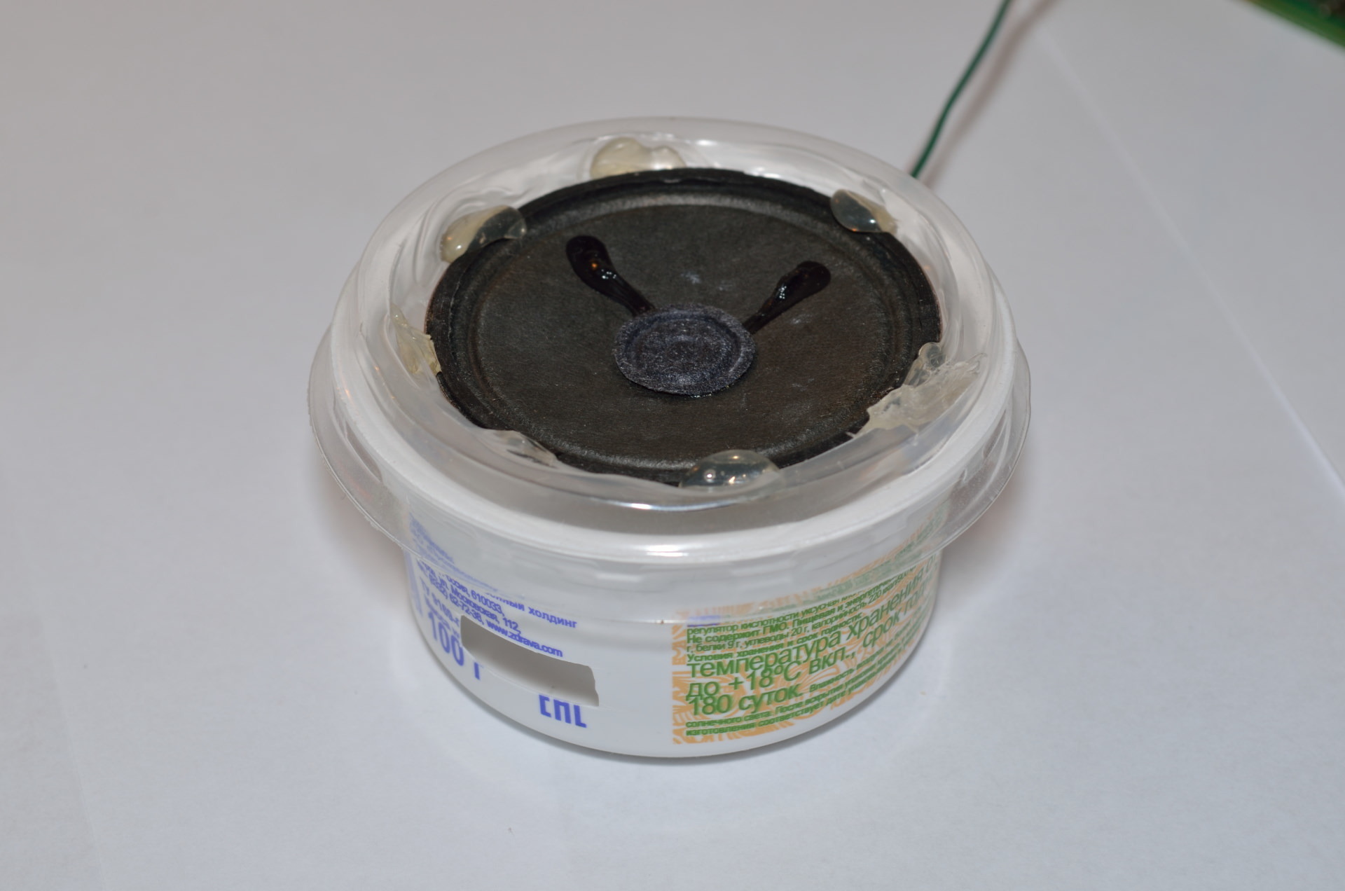
И делаю колонку с фазоинвертором:
Пора послушать:
Звучит более-менее терпимо, если подключить динамик побольше становится получше.
// I/O Registers definitions
#include <io.h>

// Declare your global variables here
#define fSIZE 12000
int rAdr,wAdr,dn;
char needdata;
char fifo[fSIZE];
// System Clocks initialization
void system_clocks_init(void)
{
unsigned char n,s;

// Optimize for speed
#pragma optsize-
// Save interrupts enabled/disabled state
s=SREG;
// Disable interrupts
#asm("cli")

// External 16000,000 kHz oscillator initialization
// External Clock Source - Startup Time: 0.4-16 MHz Quartz Crystal - 16k CLK
OSC.XOSCCTRL=OSC_FRQRANGE_12TO16_gc | OSC_XOSCSEL_XTAL_16KCLK_gc;
// Enable the external oscillator/clock source
OSC.CTRL|=OSC_XOSCEN_bm;

// System Clock prescaler A division factor: 1
// System Clock prescalers B & C division factors: B:1, C:1
// ClkPer4: 16000,000 kHz
// ClkPer2: 16000,000 kHz
// ClkPer:  16000,000 kHz
// ClkCPU:  16000,000 kHz
n=(CLK.PSCTRL & (~(CLK_PSADIV_gm | CLK_PSBCDIV1_bm | CLK_PSBCDIV0_bm))) |
	CLK_PSADIV_1_gc | CLK_PSBCDIV_1_1_gc;
CCP=CCP_IOREG_gc;
CLK.PSCTRL=n;

// Wait for the external oscillator to stabilize
while ((OSC.STATUS & OSC_XOSCRDY_bm)==0);

// Select the system clock source: External Oscillator or Clock
n=(CLK.CTRL & (~CLK_SCLKSEL_gm)) | CLK_SCLKSEL_XOSC_gc;
CCP=CCP_IOREG_gc;
CLK.CTRL=n;

// Disable the unused oscillators: 2 MHz, 32 MHz, internal 32 kHz, PLL
OSC.CTRL&= ~(OSC_RC2MEN_bm | OSC_RC32MEN_bm | OSC_RC32KEN_bm | OSC_PLLEN_bm);

// ClkPer output disabled
PORTCFG.CLKEVOUT&= ~(PORTCFG_CLKOUTSEL_gm | PORTCFG_CLKOUT_gm);
// Restore interrupts enabled/disabled state
SREG=s;
// Restore optimization for size if needed
#pragma optsize_default
}

// Ports initialization
void ports_init(void)
{
// PORTA initialization
// OUT register
PORTA.OUT=0x00;
// Pin0: Input
// Pin1: Input
// Pin2: Input
// Pin3: Input
// Pin4: Input
// Pin5: Input
// Pin6: Input
// Pin7: Input
PORTA.DIR=0x00;
// Pin0 Output/Pull configuration: Totempole/No
// Pin0 Input/Sense configuration: Sense both edges
// Pin0 Inverted: Off
// Pin0 Slew Rate Limitation: Off
PORTA.PIN0CTRL=PORT_OPC_TOTEM_gc | PORT_ISC_BOTHEDGES_gc;
// Pin1 Output/Pull configuration: Totempole/No
// Pin1 Input/Sense configuration: Sense both edges
// Pin1 Inverted: Off
// Pin1 Slew Rate Limitation: Off
PORTA.PIN1CTRL=PORT_OPC_TOTEM_gc | PORT_ISC_BOTHEDGES_gc;
// Pin2 Output/Pull configuration: Totempole/No
// Pin2 Input/Sense configuration: Sense both edges
// Pin2 Inverted: Off
// Pin2 Slew Rate Limitation: Off
PORTA.PIN2CTRL=PORT_OPC_TOTEM_gc | PORT_ISC_BOTHEDGES_gc;
// Pin3 Output/Pull configuration: Totempole/No
// Pin3 Input/Sense configuration: Sense both edges
// Pin3 Inverted: Off
// Pin3 Slew Rate Limitation: Off
PORTA.PIN3CTRL=PORT_OPC_TOTEM_gc | PORT_ISC_BOTHEDGES_gc;
// Pin4 Output/Pull configuration: Totempole/No
// Pin4 Input/Sense configuration: Sense both edges
// Pin4 Inverted: Off
// Pin4 Slew Rate Limitation: Off
PORTA.PIN4CTRL=PORT_OPC_TOTEM_gc | PORT_ISC_BOTHEDGES_gc;
// Pin5 Output/Pull configuration: Totempole/No
// Pin5 Input/Sense configuration: Sense both edges
// Pin5 Inverted: Off
// Pin5 Slew Rate Limitation: Off
PORTA.PIN5CTRL=PORT_OPC_TOTEM_gc | PORT_ISC_BOTHEDGES_gc;
// Pin6 Output/Pull configuration: Totempole/No
// Pin6 Input/Sense configuration: Sense both edges
// Pin6 Inverted: Off
// Pin6 Slew Rate Limitation: Off
PORTA.PIN6CTRL=PORT_OPC_TOTEM_gc | PORT_ISC_BOTHEDGES_gc;
// Pin7 Output/Pull configuration: Totempole/No
// Pin7 Input/Sense configuration: Sense both edges
// Pin7 Inverted: Off
// Pin7 Slew Rate Limitation: Off
PORTA.PIN7CTRL=PORT_OPC_TOTEM_gc | PORT_ISC_BOTHEDGES_gc;
// Interrupt 0 level: Disabled
// Interrupt 1 level: Disabled
PORTA.INTCTRL=(PORTA.INTCTRL & (~(PORT_INT1LVL_gm | PORT_INT0LVL_gm))) |
	PORT_INT1LVL_OFF_gc | PORT_INT0LVL_OFF_gc;
// Pin0 Pin Change interrupt 0: Off
// Pin1 Pin Change interrupt 0: Off
// Pin2 Pin Change interrupt 0: Off
// Pin3 Pin Change interrupt 0: Off
// Pin4 Pin Change interrupt 0: Off
// Pin5 Pin Change interrupt 0: Off
// Pin6 Pin Change interrupt 0: Off
// Pin7 Pin Change interrupt 0: Off
PORTA.INT0MASK=0x00;
// Pin0 Pin Change interrupt 1: Off
// Pin1 Pin Change interrupt 1: Off
// Pin2 Pin Change interrupt 1: Off
// Pin3 Pin Change interrupt 1: Off
// Pin4 Pin Change interrupt 1: Off
// Pin5 Pin Change interrupt 1: Off
// Pin6 Pin Change interrupt 1: Off
// Pin7 Pin Change interrupt 1: Off
PORTA.INT1MASK=0x00;

// PORTB initialization
// OUT register
PORTB.OUT=0x00;
// Pin0: Input
// Pin1: Input
// Pin2: Input
// Pin3: Input
// Pin4: Input
// Pin5: Input
// Pin6: Input
// Pin7: Input
PORTB.DIR=0x00;
// Pin0 Output/Pull configuration: Totempole/No
// Pin0 Input/Sense configuration: Sense both edges
// Pin0 Inverted: Off
// Pin0 Slew Rate Limitation: Off
PORTB.PIN0CTRL=PORT_OPC_TOTEM_gc | PORT_ISC_BOTHEDGES_gc;
// Pin1 Output/Pull configuration: Totempole/No
// Pin1 Input/Sense configuration: Sense both edges
// Pin1 Inverted: Off
// Pin1 Slew Rate Limitation: Off
PORTB.PIN1CTRL=PORT_OPC_TOTEM_gc | PORT_ISC_BOTHEDGES_gc;
// Pin2 Output/Pull configuration: Totempole/No
// Pin2 Input/Sense configuration: Sense both edges
// Pin2 Inverted: Off
// Pin2 Slew Rate Limitation: Off
PORTB.PIN2CTRL=PORT_OPC_TOTEM_gc | PORT_ISC_BOTHEDGES_gc;
// Pin3 Output/Pull configuration: Totempole/No
// Pin3 Input/Sense configuration: Sense both edges
// Pin3 Inverted: Off
// Pin3 Slew Rate Limitation: Off
PORTB.PIN3CTRL=PORT_OPC_TOTEM_gc | PORT_ISC_BOTHEDGES_gc;
// Pin4 Output/Pull configuration: Totempole/No
// Pin4 Input/Sense configuration: Sense both edges
// Pin4 Inverted: Off
// Pin4 Slew Rate Limitation: Off
PORTB.PIN4CTRL=PORT_OPC_TOTEM_gc | PORT_ISC_BOTHEDGES_gc;
// Pin5 Output/Pull configuration: Totempole/No
// Pin5 Input/Sense configuration: Sense both edges
// Pin5 Inverted: Off
// Pin5 Slew Rate Limitation: Off
PORTB.PIN5CTRL=PORT_OPC_TOTEM_gc | PORT_ISC_BOTHEDGES_gc;
// Pin6 Output/Pull configuration: Totempole/No
// Pin6 Input/Sense configuration: Sense both edges
// Pin6 Inverted: Off
// Pin6 Slew Rate Limitation: Off
PORTB.PIN6CTRL=PORT_OPC_TOTEM_gc | PORT_ISC_BOTHEDGES_gc;
// Pin7 Output/Pull configuration: Totempole/No
// Pin7 Input/Sense configuration: Sense both edges
// Pin7 Inverted: Off
// Pin7 Slew Rate Limitation: Off
PORTB.PIN7CTRL=PORT_OPC_TOTEM_gc | PORT_ISC_BOTHEDGES_gc;
// Interrupt 0 level: Disabled
// Interrupt 1 level: Disabled
PORTB.INTCTRL=(PORTB.INTCTRL & (~(PORT_INT1LVL_gm | PORT_INT0LVL_gm))) |
	PORT_INT1LVL_OFF_gc | PORT_INT0LVL_OFF_gc;
// Pin0 Pin Change interrupt 0: Off
// Pin1 Pin Change interrupt 0: Off
// Pin2 Pin Change interrupt 0: Off
// Pin3 Pin Change interrupt 0: Off
// Pin4 Pin Change interrupt 0: Off
// Pin5 Pin Change interrupt 0: Off
// Pin6 Pin Change interrupt 0: Off
// Pin7 Pin Change interrupt 0: Off
PORTB.INT0MASK=0x00;
// Pin0 Pin Change interrupt 1: Off
// Pin1 Pin Change interrupt 1: Off
// Pin2 Pin Change interrupt 1: Off
// Pin3 Pin Change interrupt 1: Off
// Pin4 Pin Change interrupt 1: Off
// Pin5 Pin Change interrupt 1: Off
// Pin6 Pin Change interrupt 1: Off
// Pin7 Pin Change interrupt 1: Off
PORTB.INT1MASK=0x00;

// PORTC initialization
// OUT register
PORTC.OUT=0x00;
// Pin0: Input
// Pin1: Input
// Pin2: Input
// Pin3: Input
// Pin4: Input
// Pin5: Input
// Pin6: Input
// Pin7: Input
PORTC.DIR=0x00;
// Pin0 Output/Pull configuration: Totempole/No
// Pin0 Input/Sense configuration: Sense both edges
// Pin0 Inverted: Off
// Pin0 Slew Rate Limitation: Off
PORTC.PIN0CTRL=PORT_OPC_TOTEM_gc | PORT_ISC_BOTHEDGES_gc;
// Pin1 Output/Pull configuration: Totempole/No
// Pin1 Input/Sense configuration: Sense both edges
// Pin1 Inverted: Off
// Pin1 Slew Rate Limitation: Off
PORTC.PIN1CTRL=PORT_OPC_TOTEM_gc | PORT_ISC_BOTHEDGES_gc;
// Pin2 Output/Pull configuration: Totempole/No
// Pin2 Input/Sense configuration: Sense both edges
// Pin2 Inverted: Off
// Pin2 Slew Rate Limitation: Off
PORTC.PIN2CTRL=PORT_OPC_TOTEM_gc | PORT_ISC_BOTHEDGES_gc;
// Pin3 Output/Pull configuration: Totempole/No
// Pin3 Input/Sense configuration: Sense both edges
// Pin3 Inverted: Off
// Pin3 Slew Rate Limitation: Off
PORTC.PIN3CTRL=PORT_OPC_TOTEM_gc | PORT_ISC_BOTHEDGES_gc;
// Pin4 Output/Pull configuration: Totempole/No
// Pin4 Input/Sense configuration: Sense both edges
// Pin4 Inverted: Off
// Pin4 Slew Rate Limitation: Off
PORTC.PIN4CTRL=PORT_OPC_TOTEM_gc | PORT_ISC_BOTHEDGES_gc;
// Pin5 Output/Pull configuration: Totempole/No
// Pin5 Input/Sense configuration: Sense both edges
// Pin5 Inverted: Off
// Pin5 Slew Rate Limitation: Off
PORTC.PIN5CTRL=PORT_OPC_TOTEM_gc | PORT_ISC_BOTHEDGES_gc;
// Pin6 Output/Pull configuration: Totempole/No
// Pin6 Input/Sense configuration: Sense both edges
// Pin6 Inverted: Off
// Pin6 Slew Rate Limitation: Off
PORTC.PIN6CTRL=PORT_OPC_TOTEM_gc | PORT_ISC_BOTHEDGES_gc;
// Pin7 Output/Pull configuration: Totempole/No
// Pin7 Input/Sense configuration: Sense both edges
// Pin7 Inverted: Off
// Pin7 Slew Rate Limitation: Off
PORTC.PIN7CTRL=PORT_OPC_TOTEM_gc | PORT_ISC_BOTHEDGES_gc;
// PORTC Peripheral Output Remapping
// OC0A Output: Pin 0
// OC0B Output: Pin 1
// OC0C Output: Pin 2
// OC0D Output: Pin 3
// USART0 XCK: Pin 1
// USART0 RXD: Pin 2
// USART0 TXD: Pin 3
// SPI MOSI: Pin 5
// SPI SCK: Pin 7
PORTC.REMAP=(0<<PORT_SPI_bp) | (0<<PORT_USART0_bp) | (0<<PORT_TC0D_bp) | (0<<PORT_TC0C_bp) | (0<<PORT_TC0B_bp) | (0<<PORT_TC0A_bp);
// Interrupt 0 level: Disabled
// Interrupt 1 level: Disabled
PORTC.INTCTRL=(PORTC.INTCTRL & (~(PORT_INT1LVL_gm | PORT_INT0LVL_gm))) |
	PORT_INT1LVL_OFF_gc | PORT_INT0LVL_OFF_gc;
// Pin0 Pin Change interrupt 0: Off
// Pin1 Pin Change interrupt 0: Off
// Pin2 Pin Change interrupt 0: Off
// Pin3 Pin Change interrupt 0: Off
// Pin4 Pin Change interrupt 0: Off
// Pin5 Pin Change interrupt 0: Off
// Pin6 Pin Change interrupt 0: Off
// Pin7 Pin Change interrupt 0: Off
PORTC.INT0MASK=0x00;
// Pin0 Pin Change interrupt 1: Off
// Pin1 Pin Change interrupt 1: Off
// Pin2 Pin Change interrupt 1: Off
// Pin3 Pin Change interrupt 1: Off
// Pin4 Pin Change interrupt 1: Off
// Pin5 Pin Change interrupt 1: Off
// Pin6 Pin Change interrupt 1: Off
// Pin7 Pin Change interrupt 1: Off
PORTC.INT1MASK=0x00;

// PORTD initialization
// OUT register
PORTD.OUT=0x00;
// Pin0: Output
// Pin1: Output
// Pin2: Output
// Pin3: Output
// Pin4: Output
// Pin5: Output
// Pin6: Output
// Pin7: Output
PORTD.DIR=0xFF;
// Pin0 Output/Pull configuration: Totempole/No
// Pin0 Input/Sense configuration: Sense both edges
// Pin0 Inverted: Off
// Pin0 Slew Rate Limitation: On
PORTD.PIN0CTRL=PORT_SRLEN_bm | PORT_OPC_TOTEM_gc | PORT_ISC_BOTHEDGES_gc;
// Pin1 Output/Pull configuration: Totempole/No
// Pin1 Input/Sense configuration: Sense both edges
// Pin1 Inverted: Off
// Pin1 Slew Rate Limitation: On
PORTD.PIN1CTRL=PORT_SRLEN_bm | PORT_OPC_TOTEM_gc | PORT_ISC_BOTHEDGES_gc;
// Pin2 Output/Pull configuration: Totempole/No
// Pin2 Input/Sense configuration: Sense both edges
// Pin2 Inverted: Off
// Pin2 Slew Rate Limitation: On
PORTD.PIN2CTRL=PORT_SRLEN_bm | PORT_OPC_TOTEM_gc | PORT_ISC_BOTHEDGES_gc;
// Pin3 Output/Pull configuration: Totempole/No
// Pin3 Input/Sense configuration: Sense both edges
// Pin3 Inverted: Off
// Pin3 Slew Rate Limitation: On
PORTD.PIN3CTRL=PORT_SRLEN_bm | PORT_OPC_TOTEM_gc | PORT_ISC_BOTHEDGES_gc;
// Pin4 Output/Pull configuration: Totempole/No
// Pin4 Input/Sense configuration: Sense both edges
// Pin4 Inverted: Off
// Pin4 Slew Rate Limitation: On
PORTD.PIN4CTRL=PORT_SRLEN_bm | PORT_OPC_TOTEM_gc | PORT_ISC_BOTHEDGES_gc;
// Pin5 Output/Pull configuration: Totempole/No
// Pin5 Input/Sense configuration: Sense both edges
// Pin5 Inverted: Off
// Pin5 Slew Rate Limitation: On
PORTD.PIN5CTRL=PORT_SRLEN_bm | PORT_OPC_TOTEM_gc | PORT_ISC_BOTHEDGES_gc;
// Pin6 Output/Pull configuration: Totempole/No
// Pin6 Input/Sense configuration: Sense both edges
// Pin6 Inverted: Off
// Pin6 Slew Rate Limitation: On
PORTD.PIN6CTRL=PORT_SRLEN_bm | PORT_OPC_TOTEM_gc | PORT_ISC_BOTHEDGES_gc;
// Pin7 Output/Pull configuration: Totempole/No
// Pin7 Input/Sense configuration: Sense both edges
// Pin7 Inverted: Off
// Pin7 Slew Rate Limitation: On
PORTD.PIN7CTRL=PORT_SRLEN_bm | PORT_OPC_TOTEM_gc | PORT_ISC_BOTHEDGES_gc;
// Interrupt 0 level: Disabled
// Interrupt 1 level: Disabled
PORTD.INTCTRL=(PORTD.INTCTRL & (~(PORT_INT1LVL_gm | PORT_INT0LVL_gm))) |
	PORT_INT1LVL_OFF_gc | PORT_INT0LVL_OFF_gc;
// Pin0 Pin Change interrupt 0: Off
// Pin1 Pin Change interrupt 0: Off
// Pin2 Pin Change interrupt 0: Off
// Pin3 Pin Change interrupt 0: Off
// Pin4 Pin Change interrupt 0: Off
// Pin5 Pin Change interrupt 0: Off
// Pin6 Pin Change interrupt 0: Off
// Pin7 Pin Change interrupt 0: Off
PORTD.INT0MASK=0x00;
// Pin0 Pin Change interrupt 1: Off
// Pin1 Pin Change interrupt 1: Off
// Pin2 Pin Change interrupt 1: Off
// Pin3 Pin Change interrupt 1: Off
// Pin4 Pin Change interrupt 1: Off
// Pin5 Pin Change interrupt 1: Off
// Pin6 Pin Change interrupt 1: Off
// Pin7 Pin Change interrupt 1: Off
PORTD.INT1MASK=0x00;

// PORTE initialization
// OUT register
PORTE.OUT=0x00;
// Pin0: Input
// Pin1: Input
// Pin2: Input
// Pin3: Input
// Pin4: Input
// Pin5: Input
// Pin6: Input
// Pin7: Input
PORTE.DIR=0x00;
// Pin0 Output/Pull configuration: Totempole/No
// Pin0 Input/Sense configuration: Sense both edges
// Pin0 Inverted: Off
// Pin0 Slew Rate Limitation: Off
PORTE.PIN0CTRL=PORT_OPC_TOTEM_gc | PORT_ISC_BOTHEDGES_gc;
// Pin1 Output/Pull configuration: Totempole/No
// Pin1 Input/Sense configuration: Sense both edges
// Pin1 Inverted: Off
// Pin1 Slew Rate Limitation: Off
PORTE.PIN1CTRL=PORT_OPC_TOTEM_gc | PORT_ISC_BOTHEDGES_gc;
// Pin2 Output/Pull configuration: Totempole/No
// Pin2 Input/Sense configuration: Sense both edges
// Pin2 Inverted: Off
// Pin2 Slew Rate Limitation: Off
PORTE.PIN2CTRL=PORT_OPC_TOTEM_gc | PORT_ISC_BOTHEDGES_gc;
// Pin3 Output/Pull configuration: Totempole/No
// Pin3 Input/Sense configuration: Sense both edges
// Pin3 Inverted: Off
// Pin3 Slew Rate Limitation: Off
PORTE.PIN3CTRL=PORT_OPC_TOTEM_gc | PORT_ISC_BOTHEDGES_gc;
// Pin4 Output/Pull configuration: Totempole/No
// Pin4 Input/Sense configuration: Sense both edges
// Pin4 Inverted: Off
// Pin4 Slew Rate Limitation: Off
PORTE.PIN4CTRL=PORT_OPC_TOTEM_gc | PORT_ISC_BOTHEDGES_gc;
// Pin5 Output/Pull configuration: Totempole/No
// Pin5 Input/Sense configuration: Sense both edges
// Pin5 Inverted: Off
// Pin5 Slew Rate Limitation: Off
PORTE.PIN5CTRL=PORT_OPC_TOTEM_gc | PORT_ISC_BOTHEDGES_gc;
// Pin6 Output/Pull configuration: Totempole/No
// Pin6 Input/Sense configuration: Sense both edges
// Pin6 Inverted: Off
// Pin6 Slew Rate Limitation: Off
PORTE.PIN6CTRL=PORT_OPC_TOTEM_gc | PORT_ISC_BOTHEDGES_gc;
// Pin7 Output/Pull configuration: Totempole/No
// Pin7 Input/Sense configuration: Sense both edges
// Pin7 Inverted: Off
// Pin7 Slew Rate Limitation: Off
PORTE.PIN7CTRL=PORT_OPC_TOTEM_gc | PORT_ISC_BOTHEDGES_gc;
// Interrupt 0 level: Disabled
// Interrupt 1 level: Disabled
PORTE.INTCTRL=(PORTE.INTCTRL & (~(PORT_INT1LVL_gm | PORT_INT0LVL_gm))) |
	PORT_INT1LVL_OFF_gc | PORT_INT0LVL_OFF_gc;
// Pin0 Pin Change interrupt 0: Off
// Pin1 Pin Change interrupt 0: Off
// Pin2 Pin Change interrupt 0: Off
// Pin3 Pin Change interrupt 0: Off
// Pin4 Pin Change interrupt 0: Off
// Pin5 Pin Change interrupt 0: Off
// Pin6 Pin Change interrupt 0: Off
// Pin7 Pin Change interrupt 0: Off
PORTE.INT0MASK=0x00;
// Pin0 Pin Change interrupt 1: Off
// Pin1 Pin Change interrupt 1: Off
// Pin2 Pin Change interrupt 1: Off
// Pin3 Pin Change interrupt 1: Off
// Pin4 Pin Change interrupt 1: Off
// Pin5 Pin Change interrupt 1: Off
// Pin6 Pin Change interrupt 1: Off
// Pin7 Pin Change interrupt 1: Off
PORTE.INT1MASK=0x00;

// PORTF initialization
// OUT register
PORTF.OUT=0x08;
// Pin0: Input
// Pin1: Input
// Pin2: Input
// Pin3: Output
// Pin4: Input
// Pin5: Input
// Pin6: Input
// Pin7: Input
PORTF.DIR=0x08;
// Pin0 Output/Pull configuration: Totempole/No
// Pin0 Input/Sense configuration: Sense both edges
// Pin0 Inverted: Off
// Pin0 Slew Rate Limitation: Off
PORTF.PIN0CTRL=PORT_OPC_TOTEM_gc | PORT_ISC_BOTHEDGES_gc;
// Pin1 Output/Pull configuration: Totempole/No
// Pin1 Input/Sense configuration: Sense both edges
// Pin1 Inverted: Off
// Pin1 Slew Rate Limitation: Off
PORTF.PIN1CTRL=PORT_OPC_TOTEM_gc | PORT_ISC_BOTHEDGES_gc;
// Pin2 Output/Pull configuration: Totempole/No
// Pin2 Input/Sense configuration: Sense both edges
// Pin2 Inverted: Off
// Pin2 Slew Rate Limitation: Off
PORTF.PIN2CTRL=PORT_OPC_TOTEM_gc | PORT_ISC_BOTHEDGES_gc;
// Pin3 Output/Pull configuration: Totempole/No
// Pin3 Input/Sense configuration: Sense both edges
// Pin3 Inverted: Off
// Pin3 Slew Rate Limitation: Off
PORTF.PIN3CTRL=PORT_OPC_TOTEM_gc | PORT_ISC_BOTHEDGES_gc;
// Pin4 Output/Pull configuration: Totempole/No
// Pin4 Input/Sense configuration: Sense both edges
// Pin4 Inverted: Off
// Pin4 Slew Rate Limitation: Off
PORTF.PIN4CTRL=PORT_OPC_TOTEM_gc | PORT_ISC_BOTHEDGES_gc;
// Pin5 Output/Pull configuration: Totempole/No
// Pin5 Input/Sense configuration: Sense both edges
// Pin5 Inverted: Off
// Pin5 Slew Rate Limitation: Off
PORTF.PIN5CTRL=PORT_OPC_TOTEM_gc | PORT_ISC_BOTHEDGES_gc;
// Pin6 Output/Pull configuration: Totempole/No
// Pin6 Input/Sense configuration: Sense both edges
// Pin6 Inverted: Off
// Pin6 Slew Rate Limitation: Off
PORTF.PIN6CTRL=PORT_OPC_TOTEM_gc | PORT_ISC_BOTHEDGES_gc;
// Pin7 Output/Pull configuration: Totempole/No
// Pin7 Input/Sense configuration: Sense both edges
// Pin7 Inverted: Off
// Pin7 Slew Rate Limitation: Off
PORTF.PIN7CTRL=PORT_OPC_TOTEM_gc | PORT_ISC_BOTHEDGES_gc;
// Interrupt 0 level: Disabled
// Interrupt 1 level: Disabled
PORTF.INTCTRL=(PORTF.INTCTRL & (~(PORT_INT1LVL_gm | PORT_INT0LVL_gm))) |
	PORT_INT1LVL_OFF_gc | PORT_INT0LVL_OFF_gc;
// Pin0 Pin Change interrupt 0: Off
// Pin1 Pin Change interrupt 0: Off
// Pin2 Pin Change interrupt 0: Off
// Pin3 Pin Change interrupt 0: Off
// Pin4 Pin Change interrupt 0: Off
// Pin5 Pin Change interrupt 0: Off
// Pin6 Pin Change interrupt 0: Off
// Pin7 Pin Change interrupt 0: Off
PORTF.INT0MASK=0x00;
// Pin0 Pin Change interrupt 1: Off
// Pin1 Pin Change interrupt 1: Off
// Pin2 Pin Change interrupt 1: Off
// Pin3 Pin Change interrupt 1: Off
// Pin4 Pin Change interrupt 1: Off
// Pin5 Pin Change interrupt 1: Off
// Pin6 Pin Change interrupt 1: Off
// Pin7 Pin Change interrupt 1: Off
PORTF.INT1MASK=0x00;

// PORTR initialization
// OUT register
PORTR.OUT=0x00;
// Pin0: Input
// Pin1: Input
PORTR.DIR=0x00;
// Pin0 Output/Pull configuration: Totempole/No
// Pin0 Input/Sense configuration: Sense both edges
// Pin0 Inverted: Off
// Pin0 Slew Rate Limitation: Off
PORTR.PIN0CTRL=PORT_OPC_TOTEM_gc | PORT_ISC_BOTHEDGES_gc;
// Pin1 Output/Pull configuration: Totempole/No
// Pin1 Input/Sense configuration: Sense both edges
// Pin1 Inverted: Off
// Pin1 Slew Rate Limitation: Off
PORTR.PIN1CTRL=PORT_OPC_TOTEM_gc | PORT_ISC_BOTHEDGES_gc;
// Interrupt 0 level: Disabled
// Interrupt 1 level: Disabled
PORTR.INTCTRL=(PORTR.INTCTRL & (~(PORT_INT1LVL_gm | PORT_INT0LVL_gm))) |
	PORT_INT1LVL_OFF_gc | PORT_INT0LVL_OFF_gc;
// Pin0 Pin Change interrupt 0: Off
// Pin1 Pin Change interrupt 0: Off
PORTR.INT0MASK=0x00;
// Pin0 Pin Change interrupt 1: Off
// Pin1 Pin Change interrupt 1: Off
PORTR.INT1MASK=0x00;
}

// Virtual Ports initialization
void vports_init(void)
{
// PORTA mapped to VPORT0
// PORTB mapped to VPORT1
PORTCFG.VPCTRLA=PORTCFG_VP13MAP_PORTB_gc | PORTCFG_VP02MAP_PORTA_gc;
// PORTC mapped to VPORT2
// PORTD mapped to VPORT3
PORTCFG.VPCTRLB=PORTCFG_VP13MAP_PORTD_gc | PORTCFG_VP02MAP_PORTC_gc;
}

// Disable a Timer/Counter type TC0
void tc0_disable(TC0_t *ptc)
{
// Timer/Counter off
ptc->CTRLA=TC_CLKSEL_OFF_gc;
// Issue a reset command
ptc->CTRLFSET=TC_CMD_RESET_gc;
}

// Timer/Counter TCC0 initialization
void tcc0_init(void)
{
unsigned char s;
unsigned char n;

// Note: The correct PORTC direction for the Compare Channels
// outputs is configured in the ports_init function.

// Save interrupts enabled/disabled state
s=SREG;
// Disable interrupts
#asm("cli")

// Disable and reset the timer/counter just to be sure
tc0_disable(&TCC0);
// Clock source: ClkPer/1
TCC0.CTRLA=TC_CLKSEL_DIV1_gc;
// Mode: Normal Operation, Overflow Int./Event on TOP
// Compare/Capture on channel A: Off
// Compare/Capture on channel B: Off
// Compare/Capture on channel C: Off
// Compare/Capture on channel D: Off
TCC0.CTRLB=(0<<TC0_CCDEN_bp) | (0<<TC0_CCCEN_bp) | (0<<TC0_CCBEN_bp) | (0<<TC0_CCAEN_bp) |
	TC_WGMODE_NORMAL_gc;
// Capture event source: None
// Capture event action: None
TCC0.CTRLD=TC_EVACT_OFF_gc | TC_EVSEL_OFF_gc;

// Set Timer/Counter in Normal mode
TCC0.CTRLE=TC_BYTEM_NORMAL_gc;

// Overflow interrupt: High Level
// Error interrupt: Disabled
TCC0.INTCTRLA=TC_ERRINTLVL_OFF_gc | TC_OVFINTLVL_HI_gc;

// Compare/Capture channel A interrupt: Disabled
// Compare/Capture channel B interrupt: Disabled
// Compare/Capture channel C interrupt: Disabled
// Compare/Capture channel D interrupt: Disabled
TCC0.INTCTRLB=TC_CCDINTLVL_OFF_gc | TC_CCCINTLVL_OFF_gc | TC_CCBINTLVL_OFF_gc | TC_CCAINTLVL_OFF_gc;

// High resolution extension: Off
HIRESC.CTRLA&= ~HIRES_HREN0_bm;

// Advanced Waveform Extension initialization
// Optimize for speed
#pragma optsize-
// Disable locking the AWEX configuration registers just to be sure
n=MCU.AWEXLOCK & (~MCU_AWEXCLOCK_bm);
CCP=CCP_IOREG_gc;
MCU.AWEXLOCK=n;
// Restore optimization for size if needed
#pragma optsize_default

// Pattern generation: Off
// Dead time insertion: Off
AWEXC.CTRL=(0<<AWEX_PGM_bp) | (0<<AWEX_CWCM_bp) | (0<<AWEX_DTICCDEN_bp) | (0<<AWEX_DTICCCEN_bp) |
	(0<<AWEX_DTICCBEN_bp) | (0<<AWEX_DTICCAEN_bp);

// Fault protection initialization
// Fault detection on OCD Break detection: On
// Fault detection restart mode: Latched Mode
// Fault detection action: None (Fault protection disabled)
AWEXC.FDCTRL=(AWEXC.FDCTRL & (~(AWEX_FDDBD_bm | AWEX_FDMODE_bm | AWEX_FDACT_gm))) |
	(0<<AWEX_FDDBD_bp) | (0<<AWEX_FDMODE_bp) | AWEX_FDACT_NONE_gc;
// Fault detect events:
// Event channel 0: Off
// Event channel 1: Off
// Event channel 2: Off
// Event channel 3: Off
// Event channel 4: Off
// Event channel 5: Off
// Event channel 6: Off
// Event channel 7: Off
AWEXC.FDEMASK=0b00000000;
// Make sure the fault detect flag is cleared
AWEXC.STATUS|=AWEXC.STATUS & AWEX_FDF_bm;

// Clear the interrupt flags
TCC0.INTFLAGS=TCC0.INTFLAGS;
// Set Counter register
TCC0.CNT=0x0000;
// Set Period register
TCC0.PER=0x016A;//0x01B2;
// Set channel A Compare/Capture register
TCC0.CCA=0x0000;
// Set channel B Compare/Capture register
TCC0.CCB=0x0000;
// Set channel C Compare/Capture register
TCC0.CCC=0x0000;
// Set channel D Compare/Capture register
TCC0.CCD=0x0000;

// Restore interrupts enabled/disabled state
SREG=s;
}

// USARTF0 initialization
void usartf0_init(void)
{
// Note: The correct PORTF direction for the RxD, TxD and XCK signals
// is configured in the ports_init function.

// Transmitter is enabled
// Set TxD=1
PORTF.OUTSET=0x08;

// Communication mode: Asynchronous USART
// Data bits: 8
// Stop bits: 1
// Parity: Disabled
USARTF0.CTRLC=USART_CMODE_ASYNCHRONOUS_gc | USART_PMODE_DISABLED_gc | USART_CHSIZE_8BIT_gc;

// Receive complete interrupt: Disabled
// Transmit complete interrupt: Disabled
// Data register empty interrupt: Disabled
USARTF0.CTRLA=(USARTF0.CTRLA & (~(USART_RXCINTLVL_gm | USART_TXCINTLVL_gm | USART_DREINTLVL_gm))) |
	USART_RXCINTLVL_OFF_gc | USART_TXCINTLVL_OFF_gc | USART_DREINTLVL_OFF_gc;

// Required Baud rate: 2000000
// Real Baud Rate: 2000000,0 (x2 Mode), Error: 0,0 %
USARTF0.BAUDCTRLA=0x00;
USARTF0.BAUDCTRLB=((0x09 << USART_BSCALE_gp) & USART_BSCALE_gm) | 0x00;

// Receiver: On
// Transmitter: On
// Double transmission speed mode: On
// Multi-processor communication mode: Off
USARTF0.CTRLB=(USARTF0.CTRLB & (~(USART_RXEN_bm | USART_TXEN_bm | USART_CLK2X_bm | USART_MPCM_bm | USART_TXB8_bm))) |
	USART_RXEN_bm | USART_TXEN_bm | USART_CLK2X_bm;
}

// Receive a character from USARTF0
#pragma used+
char getchar_usartf0(void)
{
char data;
unsigned char status;

while (1)
      {
      while (((status=USARTF0.STATUS) & USART_RXCIF_bm) == 0);
      data=USARTF0.DATA;
      if ((status & (USART_FERR_bm | USART_PERR_bm | USART_BUFOVF_bm)) == 0) return data;
      }
}
#pragma used-

// Write a character to the USARTF0 Transmitter
#pragma used+
void putchar_usartf0(char c)
{
while ((USARTF0.STATUS & USART_DREIF_bm) == 0);
USARTF0.DATA=c;
}
#pragma used-

// DACB initialization
void dacb_init(void)
{
// Operating mode: Single Channel (Ch0)
// Channel 0 triggered by the event system: Off
DACB.CTRLB=(DACB.CTRLB & (~(DAC_CHSEL_gm | DAC_CH0TRIG_bm | DAC_CH1TRIG_bm))) |
	DAC_CHSEL_SINGLE_gc;

// Reference: AVcc
// Left adjust value: Off
DACB.CTRLC=(DACB.CTRLC & (~(DAC_REFSEL_gm | DAC_LEFTADJ_bm))) |
	DAC_REFSEL_AVCC_gc;

// DACB is enabled
// Low power mode: Off
// Channel 0 output: On
// Channel 1 output: Off
// Internal output connected to the ADCB and Analog Comparator MUX-es: Off
DACB.CTRLA=(DACB.CTRLA & (~(DAC_IDOEN_bm | DAC_CH0EN_bm | DAC_CH1EN_bm | DAC_LPMODE_bm))) |
	DAC_CH0EN_bm | DAC_ENABLE_bm;
}

// Function used to write data to a DACB channel ch
void dacb_write(unsigned char ch, unsigned int data)
{
register unsigned char m=ch ? DAC_CH1DRE_bm : DAC_CH0DRE_bm;
// Wait for the channel data register to be ready for new data
while ((DACB.STATUS & m)==0);
// Write new data to the channel data register
if (m==DAC_CH1DRE_bm) DACB.CH1DATA=data;
else DACB.CH0DATA=data;
}


// Timer/counter TCC0 Overflow/Underflow interrupt service routine
interrupt [TCC0_OVF_vect] void tcc0_overflow_isr(void)
{
    //PORTD.OUT=~PORTD.OUT;
   if (rAdr!=wAdr)
   {
        PORTD.OUT=fifo[rAdr++];
        //DACB.CH0DATA=fifo[rAdr++]<<4;

     //   PORTE.OUT=0;
   }
   //else
  //  PORTE.OUT=1;
   if (fSIZE==rAdr) rAdr=0;
   if (!needdata)
   {
       if (rAdr<=wAdr)
           if (wAdr-rAdr<6000)
           {
            putchar_usartf0(0xFF);
            needdata=1;
           }
           else;
           else if (rAdr-wAdr>6000)
           {
            putchar_usartf0(0xFF);
            needdata=1;
           }
   }
   else
   {
    if (dn++>2000)
    {
    putchar_usartf0(0xFF);
    dn=0;
    }
   }
}


void main(void)
{
// Declare your local variables here
unsigned char n;

// Interrupt system initialization
// Optimize for speed
#pragma optsize-
// Make sure the interrupts are disabled
#asm("cli")
// Low level interrupt: Off
// Round-robin scheduling for low level interrupt: Off
// Medium level interrupt: Off
// High level interrupt: On
// The interrupt vectors will be placed at the start of the Application FLASH section
n=(PMIC.CTRL & (~(PMIC_RREN_bm | PMIC_IVSEL_bm | PMIC_HILVLEN_bm | PMIC_MEDLVLEN_bm | PMIC_LOLVLEN_bm))) |
    PMIC_HILVLEN_bm;
CCP=CCP_IOREG_gc;
PMIC.CTRL=n;
// Set the default priority for round-robin scheduling
PMIC.INTPRI=0x00;
// Restore optimization for size if needed
#pragma optsize_default

// System clocks initialization
system_clocks_init();

// Ports initialization
ports_init();

// Virtual Ports initialization
vports_init();

// DACB initialization
dacb_init();


// Timer/Counter TCC0 initialization
tcc0_init();

// USARTF0 initialization
usartf0_init();


// Globally enable interrupts
#asm("sei")
rAdr=0;
wAdr=0;
PORTD.OUT=0xFF;
 needdata=0;
while (1)
      {
        fifo[wAdr++]=getchar_usartf0();
        if (fSIZE==wAdr) wAdr=0;
      }
}
using System;
using System.Collections.Generic;
using System.ComponentModel;
using System.Data;
using System.Drawing;
using System.Linq;
using System.Text;
using System.Threading.Tasks;
using System.Windows.Forms;
using System.IO;
using System.Text.RegularExpressions;
using System.Globalization;
using System.IO.Ports;

namespace bol
{
    public partial class Form1 : Form
    {
        public Form1()
        {
            InitializeComponent();
        }
        byte[] byData;
        int k = 0;

        private void Form1_Shown(object sender, EventArgs e)
        {
            string[] ports = SerialPort.GetPortNames();
            comboBox1.Items.AddRange(SerialPort.GetPortNames());
            if (comboBox1.Items.Count > -1)
            {
                comboBox1.SelectedIndex = 0;
            }

        }

        private void serialPort1_DataReceived(object sender, SerialDataReceivedEventArgs e)
        {
            if (serialPort1.IsOpen)
                {
                if (byData.Length - 2000 > k)
                {
                    serialPort1.Write(byData, k, 2000);
                    k += 2000;
                }
            }
        }

        private void button2_Click(object sender, EventArgs e)
        {
            serialPort1.Close();
            button1.Enabled = true;
            try
            {
                serialPort1.BaudRate = Convert.ToInt32(textBox1.Text);
            }
            catch
            {
                MessageBox.Show("неа!!!!!!"); return;
            }

            if (openFileDialog1.ShowDialog() == System.Windows.Forms.DialogResult.OK)
            {
                string fileNam = openFileDialog1.FileName;
                FileStream fs = new FileStream(fileNam, FileMode.OpenOrCreate, FileAccess.Read);
                int len = Convert.ToInt32(fs.Length);
                byData = new byte[len];   // массив байтов
                try
                {   // файловый поток, открывает файл (при отсутсвии создает) только для чтения
                    fs.Read(byData, 44, len - 44 - 1);
                    fs.Dispose(); // освобождаем ресурсы

                }
                catch (IOException err)
                {
                    MessageBox.Show(err.Message); return;
                }
                serialPort1.Open();
                k = 0;
                if (byData.Length - 2000 > k)
                {
                    serialPort1.Write(byData, k, 2000);
                    k += 2000;
                }
            }
        }


        private void comboBox1_TextChanged(object sender, EventArgs e)
        {
            serialPort1.PortName = comboBox1.Text;
        }

        private void button3_Click(object sender, EventArgs e)
        {
            k = 0;
        }

        private void button1_Click_1(object sender, EventArgs e)
        {
            if (serialPort1.IsOpen)
            {
                serialPort1.Close();
            }
            else serialPort1.Open();
        }
    }
}
Комментарии (35)

iliasam
06.04.2016 10:09+1И все же интереснее было бы задействовать все ресурсы XMega.
Можно было запустить встроенный в контроллер ЦАП, и сравнить его с самодельным.
В ATXMEGA128A3U есть USB, так что можно было взять пример Audio Out Device из LUFA, и сделать простую USB аудиокарту.QwertyOFF
06.04.2016 11:26Встроенный ЦАП я запускал, разница на слух практически отсутствует. Контроллер сам по себе генерирует много шума, от которого я никак не избавлялся, из-за этого качество страдает.
Вот так выглядит пила с R-2R ЦАП
Картинка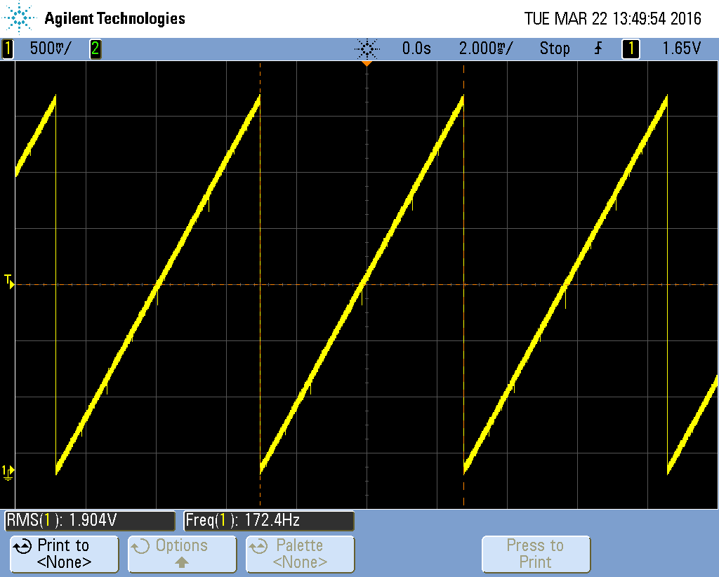

Costic
06.04.2016 18:10«точность потеряется с пятого разряда поскольку (1/2^5)<0.05», imho, вы тут заблуждаетесь.
Если упростить, то точность всей схемы ЦАП тоже будет примерно 5%. Я основываюсь на "Законе больших чисел".QwertyOFF
06.04.2016 18:41Все верно, 5 разряд изменяет напряжение на 1/32 от максимального напряжения (логической единицы), это меньше 5%, значит его использование бессмысленно.
QwertyOFF
06.04.2016 18:48Резисторы между собой неравнозначны, плохой резистор в старшем разряде сделает бессмысленным использование младших, тогда как резистор с большим отклонением в младшем разряде при идеальных остальных практически не повлияет на конечную точность.

evtomax
06.04.2016 19:16Это только при условии, что будут воспроизводиться громкие звуки.
QwertyOFF
06.04.2016 19:50Вряд ли вы найдете трек, где сигнал меньше 50% максимальной амплитуды. Как ЦАПом этой штукой уже не попользуешься, хотя играть звук будет не то чтобы ужасно.
evtomax
06.04.2016 20:08А если понадобится цифровая регулировка громкости?
QwertyOFF
06.04.2016 20:30Приведет к потере разрядности, лучше регулировать аналогово (не обязательно потенциометром, есть специальные микросхемы, управляемый цифрой).
evtomax
06.04.2016 20:57Специальная микросхема — это ещё одна микросхема.
QwertyOFF
06.04.2016 21:06Можно спорить до бесконечности, все зависит от постановки задачи и того, что нужно получить в результате. Как вариант сделать ЦАП большей разрядности на двух портах, но это еще резисторы. А вообще такие задачи правильно решать специальными микросхемами, в видео видно на заднем плане плату, там ЦАП на PCM2704 и усилитель, делал себе для замены никуда не годной звуковой карты в компьютере. Статью к сожалению уже не написать, потому что есть публикация на другом ресурсе.

MartinX
06.04.2016 21:13+1Тоже считаю, что это из разряда «из пушки по воробьям». XMEGA довольно продвинутые, могут ARM составлять конкуренцию. А обращаются с ней как с тупой Attiny, которая ничего не умеет, обвешивая UART конвертерами и R-2R матрицей.

Alexeyslav
06.04.2016 10:46Для воспроизведения коротких отрезков пойдёт, а как насчёт длинных отрезков, когда скорость поступления и скорость вывода отсчётов будет немного но отличаться? А это будет в любом случае. Нужен механизм тонкой подстройки скорости вывода так чтобы не допускать опустошения и переполнения буфера.
При разнице скорости в 20PPM например, и частоте вывода 44кГц утечка будет составлять примерно 1 отсчет в секунду. Через 1000 секунд разница между поступающим потоком и выводимым будет составлять уже порядка 1Кб…QwertyOFF
06.04.2016 11:20Как таковая скорость поступления отсчетов нигде не указана, контроллер запрашивает у ПК очередной пакет данных когда в его буфере появляется место, поэтому рассинхронизация невозможна. Я столкнулся с другой, чуть более интересной проблемой, компьютер это не тупая железяка, на нем работает ОС разделяющая процессорное время между процессами. После запроса данных контроллером они начинают высылаться не сразу, из-за этого требуется довольно большой буфер на МК.
Alexeyslav
06.04.2016 13:08+1Это недостаток такого способа воспроизведения. Но такое используют очень редко, поскольку кроме всего прочего запаздывание от входа до выхода в таких схемах определяется величиной промежуточного буфера, и чем он больше тем хуже характеристика такой схемы. Для воспроизведения одиночных сигналов это не играет особой роли, но в других случаях это довольно критично.
Поэтому, используют асинхронный вывод — сколько данных подали на вход столько и воспроизвели подстраивая скорость вывода под среднюю скорость ввода. Вот решение этой проблемы на МК и является самой интересной частью задачи, я вобщем-то ожидал именно этого.

HOMPAIN
06.04.2016 13:53А какого порядка у вас задержки? Конечно Windows не RTOS, но всё таки это не настолько критично для такой не особо затратной задачи. В шарпе ещё есть сборщик мусора, который программу стопорит на время, но это опять же порядка 10 мс(за это время накопится около 400 байт). У вас я вижу буфер в МК 12кб? Не может винда на 200 мс программу фризить.
Возможно у вас проблема с настройкой COM порта и в нём задан какой-то буфер, который шлёт данные не сразу.QwertyOFF
06.04.2016 14:03Задержку не измерял, а сейчас уже нет такой возможности. Пока подбирал размер буфера и пакета создалось впечатление что задержка составляет примерно 50 мс.
igorkozinov
06.04.2016 14:31ЦАП. Из горсти резисторов…
https://ru.wikipedia.org/wiki/Covox
Alexeyslav
06.04.2016 14:41+2Не путать, Covox это ЦАП подключаемый к параллельному порту компьютера, а здесь используется последовательный интерфейс, коих найти сейчас гораздо проще чем плату с LPT-портом под нужную встраиваемую систему. Из общего, там и правда горстка резисторов, но дальше — всё разное и даже не совместимое.
MartinX
06.04.2016 21:15Почти то же самое. Простейший ковокс — это есть 8 сигнальных цифровых линий, мы ими дрыгаем. На выходе подключаем R-2R матрицу, которая и преобразует это в аналог. Тут же мы дрыгаем ногами МК, только уже через UART конвертер.
Alexeyslav
06.04.2016 21:33Так можно любую схему с резисторным ЦАП назвать ковоксом. Нет уж, ковокс — это ЦАП именно на параллельном порту компьютера, его реализация может несколько отличаться либо это R-2R либо весовые резисторы но характерно для ковокса — именно подключение к LPT-порту компьютера или его эмулятору, который имеет программный интерфейс LPT-порта.
Ведь собственно сама идея ЦАП-а на резисторах не так уж уникальна чтобы любую схему в составе которой есть ЦАП на резисторах называть ковоксом.MartinX
06.04.2016 21:37С такой точки зрения — да. Я думаю, что igorkozinov просто приметил, что оригинальный Covox (если смотреть патент) — это так же голая R-2R матрица :). А его суть — это как из говна и палок сделать простенький вывод звука на IBM PC 80х годов (да и не только на них, все же техника тогда была дорогой).
Speccyfan
06.04.2016 15:13А еще можно читать wav с SD карты, компьютер тогда не нужен, получается портативный wav player.
QwertyOFF
06.04.2016 15:52В сети гуляет проект с SD и ЦАП на основе ШИМа, можно затолкать все это в маленький контроллер attiny.
Riniy
06.04.2016 17:36Да, лучше ШИМ, всего 1 пин занимает. Делал себе дверной звонок на SD карте с ШИМом, с частотой дискретизацией до 48кГц на меге 8. В планах на 16-битное переделать.

vassav
06.04.2016 18:04Я как-то делал дочке игрушку — читаем с SD карты wav файл и с помощью ШИМ генерил сигнал и дальше на усилитель. Получилось довольно не плохо (правда я STM использовал)
MartinX
06.04.2016 21:12Да их множество, это как помигать светодиодиком. А гуляет проект японца Elm Chan. По факту небольшая либа для работы с FAT и немного кода для софтовой реализации SPI (для работы с SD/MMC), работа таймера, обслуживающего ШИМ. Сам на межке8 делал такой проект, правда без использования FS.
Есть более интересные реализации — например, взять какую-нить Attiny13. Но там или без FS, или с простейшей: памяти маловато у этого МК. Ну еще можно найти дешевый чип памяти, хотя невостребованная SD карта небольшого по меркам телефона (до 2 гб) размера будет дешевле…

Z80A
07.04.2016 12:02Подключал TDA2822M по мостовой схеме — постоянно прут наводки, какое-то непонятное самовозбуждение, сигнала вообще не слышно. Так и не смог настроить. Собрал по стерео варианту — заработало сразу же. Мистика?
QwertyOFF
07.04.2016 17:07Если вообще не слышно сигнала — скорее всего где-то ошибка, у меня чуть-чуть пробивается 50 герц, но тут и длинный проводник, и экранирования нет Если рукой потрогать сигнальную линию, тогда 50 Гц отлично слышно.
igorkozinov
07.04.2016 16:44Долго думал, что мне напоминает схема структуры устройства в начале статьи.
Вспомнил: http://s6.hostingkartinok.com/uploads/images/2013/10/50b61037edc95b2a1160e19d44b0f609.jpg


r44083
Интересно.
P.S.: Ох уж эти эти магические цифры в коде