More on robotics.snowcron.com
First of all, this is just an exercise, useful as is, but the result is going to be far from an industrial level robots. Why doing it then?
For the same reasons we do all exercise: to get an experience. After all, when we write a character recognition «MNIST classifier» neural network, we know that the problem is solved long time ago. But we need to become familiar with tools and approaches. Same here.
Now, why is it called «brainless»?
When we hear «robotic vacuum cleaner», most of us would imagine a round thing with a bumper, wondering around the room, controlled by a simple microprocessor and acquiring the information from IR and Ultrasonic sensors as well as from the bumper (which is nothing but a touch sensor).
Let's explore a different approach. Let's have no microprocessor and no sensors at all. Still, the «platform» we are about to create will navigate around, finding its way from under the furniture, and, given time, visiting every spot, cleaning it (if we install a VC on the platform).
There is an important lesson for someone building robots: what can be done with advanced electronics, can (not always) be also done using mechanics. How?
Here is a toy, that you probably saw many times, a rather simple «platform», waiting for a VC to be installed on it.
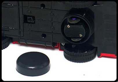
We are going to build a similar «toy», just scaled up to fit our tasks.
What we design:
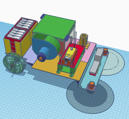
The «simple» mechanics we are about to implement is not that simple when you try to figure out how it works. It is ingenious, and so was the person who invented it. Here is the basic schematics (note: this is not a final design):
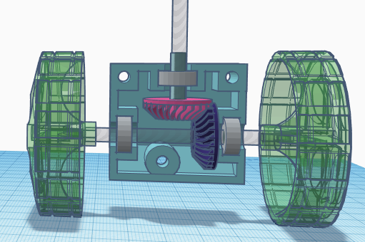
A motor is located on top of this assembly, and two conic gears are used to change the direction from wertical to horizontal. Second gear is attached to pair of wheels… that's it.
However, notice that the box holding gears is not attached to anything but motor (through vertical axe). It means that
a) the box can spin
OR
b) the wheels can spin.
If wheels do not touch the ground, the box will spin, as there is no friction to stop it from spinning.
If, however, wheels are touching the ground, spinning the box means going against the friction between wheels and ground. While wheels can spin without friction! So the device moves, hopefully (see below) forward.
Finally, if the device hits the ground, spinning the wheels means going against the friction of spinning TWO wheels on the spot (the obstacle does not allow us to move), while spinning the box… requires going against the friction of ONE wheel, as the other one spins in the same direction!
So the moment we hit the obstacle, the box with gears and wheels begins spinning. And as it spins, it tries to propel our device in changing direction. As soon as moving is possible (say, box turned 180 degrees and device moves back now), box stops spinning, and wheels begin spinning.
So as we «discover» a wall, we rotate the box, until and only until the wheels turn to the direction where there is no obstacle! Wow!
However, there is one more piece in this puzzle. Say, we hit the wall and are now going backwards. How can we turn, so that the front part of our device is in front again? And if we only turned 90 degrees, does it means we'll keep running in circles?
There are two ways of taking care of that problem. One I am going to implement, while the other is your homework. Note that most small toys use the second approach.
So we want our trajectory to only be stable if we run forward, otherwise we want to additionally rotate wheels, to make sure it is (forward). After all, if we create a toy police car, we don't want it to suddenly go backwards — forewer, or until it hits the wall!
To make our device self-adjusting, we need to introduce a bit of assymetry in it, making sure the vertical axe (one attached to the motor and conic gears) is shifted, relative to pair of wheels:

As you can see, we have added an extra axe for wheels and… And the resulting assembly will (if there is no obstacle and wheels are touching the ground) keep turning until wheels move the device «nose forward» and not backwards or in circles. It looks like this: the device hits the wall, turns (say, at 95 degrees), moves sideways and then the back wheels line up with front ones: now it runs forward!
Speaking of the rear wheels: they are idle and have no motors attached to them.
If not for the lack of space, I would call this chapter «Rough, production-not-ready design». Later, i will explain why this VC is not a perfect solution (though you probably can make it better). For now, let's simply put parts together.
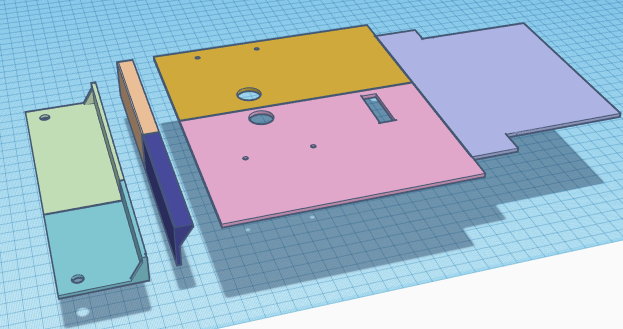
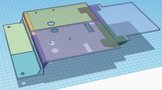
Obviously, this is the body of our «Platform for VC». But… Why is if made from pieces?
The problem with 3d printed parts is the maximum size, limited by the dimensions of a print bed: approximately, 20x20 cm. To make something bigger, we have to either use some different approach (like cutting it from the plywood), or making smaller parts and glue (screw) them together.
Middle parts will be held together by the motor compartment (see below), front oparts have shape that allows it to be glued together. To glue back part (on the right, if you look on the image) together with the rest, I use stripe of plastic (printed, too) to be glued over the connection line:
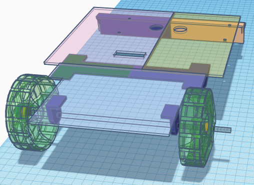
As I have already mentioned, the rear pair of wheels is passive, the spin freely as the platform moves. However, they spin together, on the same axe, so they have an additional stabilizing effect on the trajectory of our device. Note the way we attached them: a 3 mm threaded rod (available on a construction market) is held in place by printed holders. Wheels are fixed on the rod by two nuts each.
Motor was a big problem for me, as I didn't have something with proper speed. So i have added an extra reductor to a toy motor. Note that I used an easy approach: gears are held in place by bearings (cheap, available on Ali, eBay etc.)
Note that in a «big» machinery, you probably can not use standard bearing, except for easy (low load) cases to hold the axe vertical. Bearings as we know them are for horizontal axes, while vertical axes require conic bearings or something like that. A «traditional» bearing will break soon if you push on it along the axe.
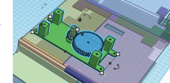
Also note the way gears are «attached» to threaded rod (or a nut if you have one that's long enough. Two nuts together on each side, of a nut melted into the plastic and an extra nut to push against it.
The way it works, when you turn two nuts «into» each other, they create sufficient pressute on a thread, so rod and two nuts kind of become one.
There are also manu ways to attach the motor to a «gear box», I chose the easiest one: i used the rubber glue. It holds well, It can be easily detached when necessary, and it is very easy on sloppy design, as you can move everything a bit before the glue holds. Note however, that I have glued the box (a motor holder), not the motor itself. It is a mater of choice, there is nothing wrong with gluing a motor.

Note also, that I could have printed the gear box as part of a device's body.
Instead I mage it separate, so that it can be screwed to the body after assembly is done. This is a good style, if you can make your device modular, do it. You will have less problems assembling and disassembling it, as a gear box is small and it is much easier to work with than the whole vacuum cleaner. Besides, maybe later you will decide to move it to another device…
We have already discussed the lower gear box.

Just few observations. First, it should be assembled as accurate as you can. No lofts.
Second… It is not going to work. Just kidding. Seriously, we shill don't have the cover of a gear box, while it has at least two «secrets»!
First of all, let's make the bottom of gear box nicer, getting rid of an ugly box-like design.
It was:
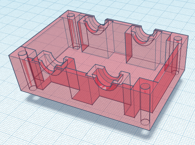
It became:
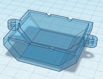
Note that the old design has slots for bearings, while a new one relies on holes in plastic. It is cheaper, it is more compact… but will it work?
A short answer is «yes», but you need to know that there are many alternatives to using bearings in such devices. You can buy (Ali!) a set of plastic (nylon, teflon) bushing, you can use drill to remove threading from a nut (and turn it into bushing) and so on.
Now, the first of two promiced secrets of the top part of the box. See, if you put some vertical pressure on the conic gears, they will move relative to each other. in other words, our gear box will rotate not only around the vertical axe (which is by design), but also around the axe wheels are on! It will look ugly, and also it will break contact between gears:
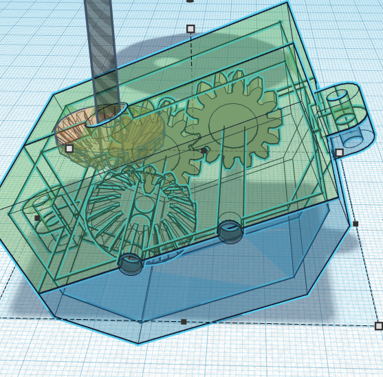
Notice that the back part of the box went up, as there are wheels, that push against the ground, lifting that part of a box, as the weifht of a device presses down on boxe's front part.
So we need to make sure the gear box still can spin, but only along vertical axe. We have a solution: let's put a pearing on it!
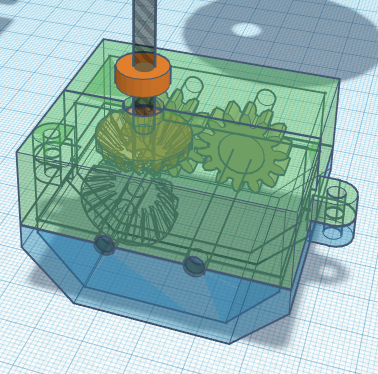
Now, in an ideal world, that would be enough. Bearing is attached to the axe (its inner part) and to the box(outer part), so we can spin, but can not shake. However, in a real world, in a 3d printed design, the bearing will not be held in place: there is, after all, a large leverage, and print is imprecise, and plastic is not rigid enough (something you can avoid using industrial formed plastic). So we need a «larger bearing», one that can counteract large leverage. And by the way, it is safe to assume that our gear box will only bend in one direction, as wheels push it there. So we need half of a bearing, so to speak.

Here we have a ring with 3 wheels attached to it (one shown). Now, we only need one wheel, as our design guarantees that the other two will never be loaded with pressure:
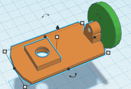
Note a little rectangle on top: it is a holder for a bearing. Now the assembly:
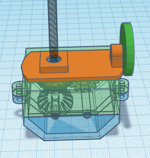
We have simply glued the wheel holder to the top of a gear box, with a bearing stick in the middle. Now the green wheel will roll over the bottom of device's body, preventing the gear box from tilting.

Holder for a power button. The power switch can be click-fit in it, for switches you have, you will have to design one of your own.

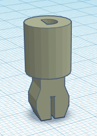
Front brushes. Tiny motors with reductors bought on Ali, spare brushes for VC, too. A plastic box to hold motors was printed. The only problem is to connect motor and brush. I have printed a connector that click-fits in the brust and tight fits on motor's axe:
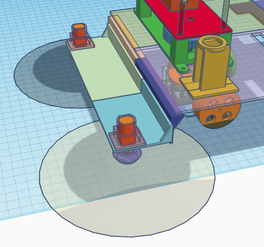
An important observation: now you know one of two reasons the front part of a Platform is low. The back it lifted, as gear box is rather tall, but we need to be close to the floow to use brushes. A second reason is, we don't need our platform to be some kind of an all terrain vehicle. We need it to turn when it meets the obstacle, not to run over it.
Batteries. For this project I use a pack of 32 NiMh accumulators (which is probably an overkill). I will talk about an electrical part later.
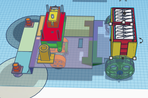
Finally, a «VC» part. I am going to design it, but I will not print it: after all, I do not need a vacuum cleaner. The way I chose parameters of a turbine is a subject for a separate article, too.
We have a choice between a fan (one that looks like a propeller of a plane) and a centrifuge compressor. The latest is <i.way better for VC, so the choice is obvious. When it comes to vacuum, a centrifuge is better, this is a general rule.
We are going to use a turbine with a rather powerful motor:

Important: this is not a final design of a turbine's rotor, as I mentioned, it is a subject of a separate article. A final design works about 3 times better than a rotor on the picture.
A turbine sucks air througn a hole in its front part (you can see it on the left) and throws air up.
A dust collector. This part is not as simple as it might seem. First of all, we need a box:
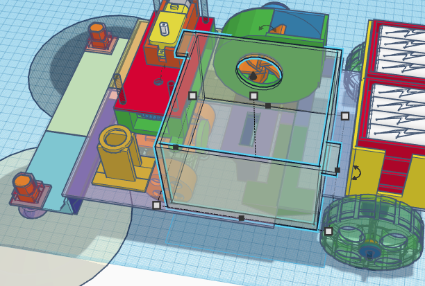
It will be glued to the base, and a front side of a compressor will be glued to it. However, we need an easy access, so that we can remove dust it collects. So the top cover is removable.
Then we need a filter. We are going to put filter into the box, so for it to fit without holes, we are going to add a support (red one):
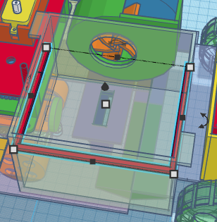
We can even attach some thin foamed plastic or fabric on top of a support, to make contact hermetic. Then we add a filter, which is a plastic frame with filter on it. As a filter, let's use electro static napkin.
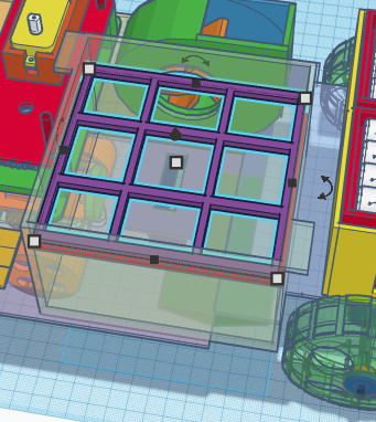
There is some space between filter and cover of the container, as well as between filter and the side of a container that faces a turbine. The space on top is ok, we need it as we suck air through the side wall, and filter faces top. But we need an extra wall facing the turbine, supporting filter:
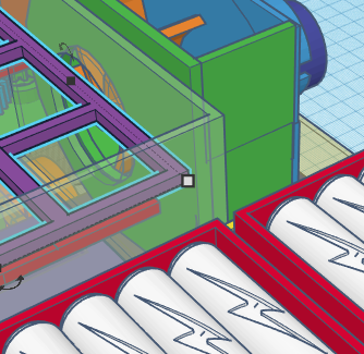
The space on top is ok, we need it as we suck air through the side wall, and filter faces top. But we need an extra wall facing the turbine, supporting filter:
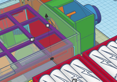
Finally, the lid, the cover we put on top of a container:
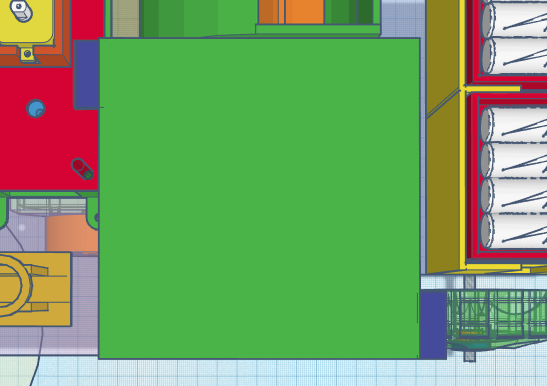
Note the dark blue rectangles attached to the lid. The box have similar parts, together they are used to close container: I chose using paper clips instead of inventing elaborated locks:

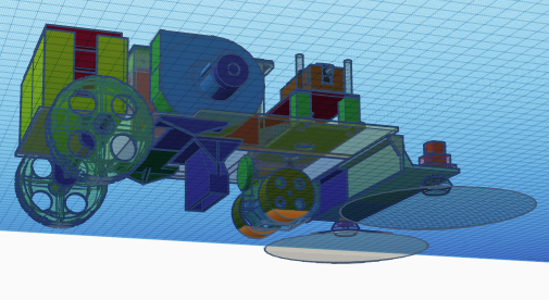
The last thing we need to address here is how the dust goes to the dust compartment. As you can see, there is a hole in the bottom of a compartment, but it is 60 mm above the ground. We want it to be 10 mm above the ground, so we need a pipe of some kind, going almost all the way down:

Same pipe in place:
Electrical part of a Platform is very simple. It includes motor, accumulators, power switch and a power convertors LM-317 and (optionally) MT3608. I will only focus on power convertors, as the rest is trivial.
What does the «optionally» means? We have two choices. Either we use only one voltage (which is 6 volts, as this is what motor requires) to feed both wheels and compressor, or we use higher voltage on the compressor's motor. The first option requires a single power convertor from whatever our battery provides to 6 volts. A battery, by the way, is composed of two parallel packs, 16 accumulators each, so the voltage is around 16*1.2=19.2 volts, when fully charged.
LM-317 is a step down convertor, it can take a range of voltages as an input and hold 6v (if we set it to 6v, it can be adjusted) as an output.
See, when an accumulator discharges, the voltage drops. So if we feed power to motors directly, it will run slower… and slower… If we had a microprocessor to power, it would be a disaster, as microprocessors require voltage to be in a certain range, if it drops (unlike with a motor) they can be damaged. While using the convertor, we can suck our accumulators dry, and still have proper voltage — till they are almost discharged.
Now, a tiny motor we use to spin wheels of our Platform does not have to be powerful: the speed is slow, the reduction rate is large. 6V is enough in this situation. Compressor is a different story. The more power we use on it, the stronger vacuum it produces. So we need to consider 9, 12, 18, 24 V motors — they are faster and yeild incomparably better results.
So we have to add a second convertor — either LM-317 connected directly to accumulators (step down, it reduces voltage), or MT3608, a step up convertor that will be connected to the output of the LM-317. It will take 6V and increase it to 9/12/… volts to feed the motor of a compressor.
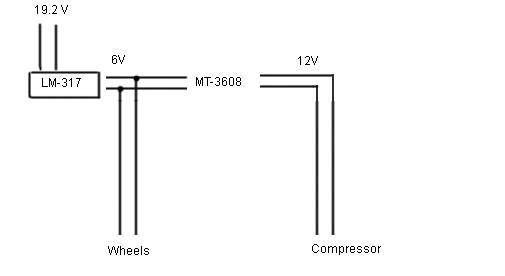
Brushes motors use 6V as well and are not shown here.
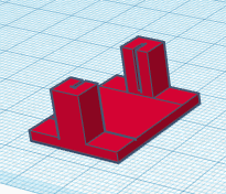
Finally, a simple holder for a power convertor. It fits there tight and holds well:
Assembling is trivial. One thing to keep in mind is that conic gears can loose contact (with each other) even when moved 1mm along its axes. So we need to use pairs of nuts to hold them in place, nuts as close to the walls of a gear box as possible:
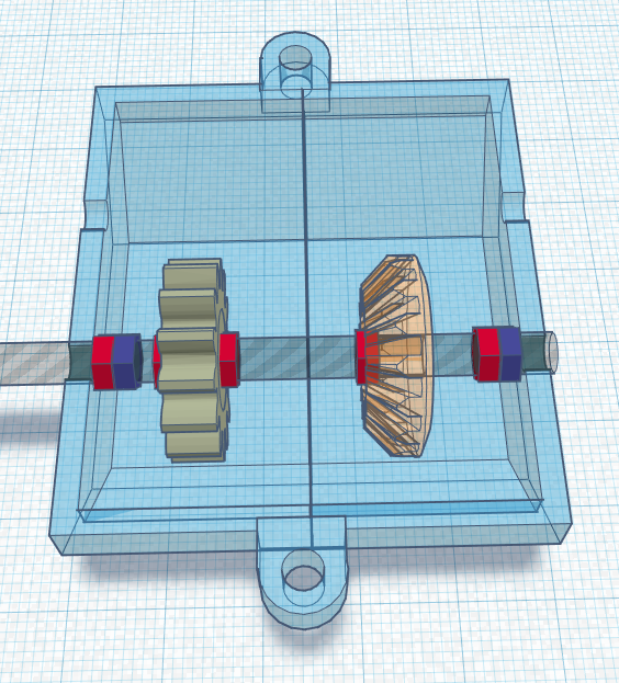
Note at the picture above, the gears are held in place with nuts and nuts at the ends of an axe (at the left and at the right) do not allow the whole installation to move right-left.
On the following video you can see a partially assembled Platform moving around the room.
So we have got the proof of a concept. Next step is to turn a prototype into a device with some commercial value. This is a step any engineer faces; no mater how good your design is, you will discover problems, half way, that are too late to fix in a beta version.
What we have to improve:
In this article we went over building a simple bump-and-run platform, intended as a vacuum cleaner or simply as a toy. In our next articles, we are going to build more complex machines with more complex behaviour and functions.
Good luck :)
First of all, this is just an exercise, useful as is, but the result is going to be far from an industrial level robots. Why doing it then?
For the same reasons we do all exercise: to get an experience. After all, when we write a character recognition «MNIST classifier» neural network, we know that the problem is solved long time ago. But we need to become familiar with tools and approaches. Same here.
Now, why is it called «brainless»?
When we hear «robotic vacuum cleaner», most of us would imagine a round thing with a bumper, wondering around the room, controlled by a simple microprocessor and acquiring the information from IR and Ultrasonic sensors as well as from the bumper (which is nothing but a touch sensor).
Let's explore a different approach. Let's have no microprocessor and no sensors at all. Still, the «platform» we are about to create will navigate around, finding its way from under the furniture, and, given time, visiting every spot, cleaning it (if we install a VC on the platform).
There is an important lesson for someone building robots: what can be done with advanced electronics, can (not always) be also done using mechanics. How?
A toy you probably saw
Here is a toy, that you probably saw many times, a rather simple «platform», waiting for a VC to be installed on it.

We are going to build a similar «toy», just scaled up to fit our tasks.
After reading this tutorial you will learn:
- How to design simple mechanical moving devices.
- How to build a simple robot.
- How to provide power for it.
What we design:

A little bit of theory
The «simple» mechanics we are about to implement is not that simple when you try to figure out how it works. It is ingenious, and so was the person who invented it. Here is the basic schematics (note: this is not a final design):

A motor is located on top of this assembly, and two conic gears are used to change the direction from wertical to horizontal. Second gear is attached to pair of wheels… that's it.
However, notice that the box holding gears is not attached to anything but motor (through vertical axe). It means that
a) the box can spin
OR
b) the wheels can spin.
If wheels do not touch the ground, the box will spin, as there is no friction to stop it from spinning.
If, however, wheels are touching the ground, spinning the box means going against the friction between wheels and ground. While wheels can spin without friction! So the device moves, hopefully (see below) forward.
Finally, if the device hits the ground, spinning the wheels means going against the friction of spinning TWO wheels on the spot (the obstacle does not allow us to move), while spinning the box… requires going against the friction of ONE wheel, as the other one spins in the same direction!
So the moment we hit the obstacle, the box with gears and wheels begins spinning. And as it spins, it tries to propel our device in changing direction. As soon as moving is possible (say, box turned 180 degrees and device moves back now), box stops spinning, and wheels begin spinning.
So as we «discover» a wall, we rotate the box, until and only until the wheels turn to the direction where there is no obstacle! Wow!
However, there is one more piece in this puzzle. Say, we hit the wall and are now going backwards. How can we turn, so that the front part of our device is in front again? And if we only turned 90 degrees, does it means we'll keep running in circles?
There are two ways of taking care of that problem. One I am going to implement, while the other is your homework. Note that most small toys use the second approach.
So we want our trajectory to only be stable if we run forward, otherwise we want to additionally rotate wheels, to make sure it is (forward). After all, if we create a toy police car, we don't want it to suddenly go backwards — forewer, or until it hits the wall!
To make our device self-adjusting, we need to introduce a bit of assymetry in it, making sure the vertical axe (one attached to the motor and conic gears) is shifted, relative to pair of wheels:

As you can see, we have added an extra axe for wheels and… And the resulting assembly will (if there is no obstacle and wheels are touching the ground) keep turning until wheels move the device «nose forward» and not backwards or in circles. It looks like this: the device hits the wall, turns (say, at 95 degrees), moves sideways and then the back wheels line up with front ones: now it runs forward!
Speaking of the rear wheels: they are idle and have no motors attached to them.
Design.
If not for the lack of space, I would call this chapter «Rough, production-not-ready design». Later, i will explain why this VC is not a perfect solution (though you probably can make it better). For now, let's simply put parts together.

Obviously, this is the body of our «Platform for VC». But… Why is if made from pieces?
The problem with 3d printed parts is the maximum size, limited by the dimensions of a print bed: approximately, 20x20 cm. To make something bigger, we have to either use some different approach (like cutting it from the plywood), or making smaller parts and glue (screw) them together.
Middle parts will be held together by the motor compartment (see below), front oparts have shape that allows it to be glued together. To glue back part (on the right, if you look on the image) together with the rest, I use stripe of plastic (printed, too) to be glued over the connection line:

As I have already mentioned, the rear pair of wheels is passive, the spin freely as the platform moves. However, they spin together, on the same axe, so they have an additional stabilizing effect on the trajectory of our device. Note the way we attached them: a 3 mm threaded rod (available on a construction market) is held in place by printed holders. Wheels are fixed on the rod by two nuts each.

Motor was a big problem for me, as I didn't have something with proper speed. So i have added an extra reductor to a toy motor. Note that I used an easy approach: gears are held in place by bearings (cheap, available on Ali, eBay etc.)
Note that in a «big» machinery, you probably can not use standard bearing, except for easy (low load) cases to hold the axe vertical. Bearings as we know them are for horizontal axes, while vertical axes require conic bearings or something like that. A «traditional» bearing will break soon if you push on it along the axe.

Also note the way gears are «attached» to threaded rod (or a nut if you have one that's long enough. Two nuts together on each side, of a nut melted into the plastic and an extra nut to push against it.
The way it works, when you turn two nuts «into» each other, they create sufficient pressute on a thread, so rod and two nuts kind of become one.
There are also manu ways to attach the motor to a «gear box», I chose the easiest one: i used the rubber glue. It holds well, It can be easily detached when necessary, and it is very easy on sloppy design, as you can move everything a bit before the glue holds. Note however, that I have glued the box (a motor holder), not the motor itself. It is a mater of choice, there is nothing wrong with gluing a motor.

Note also, that I could have printed the gear box as part of a device's body.
Instead I mage it separate, so that it can be screwed to the body after assembly is done. This is a good style, if you can make your device modular, do it. You will have less problems assembling and disassembling it, as a gear box is small and it is much easier to work with than the whole vacuum cleaner. Besides, maybe later you will decide to move it to another device…
We have already discussed the lower gear box.

Just few observations. First, it should be assembled as accurate as you can. No lofts.
Second… It is not going to work. Just kidding. Seriously, we shill don't have the cover of a gear box, while it has at least two «secrets»!
First of all, let's make the bottom of gear box nicer, getting rid of an ugly box-like design.
It was:

It became:

Note that the old design has slots for bearings, while a new one relies on holes in plastic. It is cheaper, it is more compact… but will it work?
A short answer is «yes», but you need to know that there are many alternatives to using bearings in such devices. You can buy (Ali!) a set of plastic (nylon, teflon) bushing, you can use drill to remove threading from a nut (and turn it into bushing) and so on.
Now, the first of two promiced secrets of the top part of the box. See, if you put some vertical pressure on the conic gears, they will move relative to each other. in other words, our gear box will rotate not only around the vertical axe (which is by design), but also around the axe wheels are on! It will look ugly, and also it will break contact between gears:

Notice that the back part of the box went up, as there are wheels, that push against the ground, lifting that part of a box, as the weifht of a device presses down on boxe's front part.
So we need to make sure the gear box still can spin, but only along vertical axe. We have a solution: let's put a pearing on it!

Now, in an ideal world, that would be enough. Bearing is attached to the axe (its inner part) and to the box(outer part), so we can spin, but can not shake. However, in a real world, in a 3d printed design, the bearing will not be held in place: there is, after all, a large leverage, and print is imprecise, and plastic is not rigid enough (something you can avoid using industrial formed plastic). So we need a «larger bearing», one that can counteract large leverage. And by the way, it is safe to assume that our gear box will only bend in one direction, as wheels push it there. So we need half of a bearing, so to speak.

Here we have a ring with 3 wheels attached to it (one shown). Now, we only need one wheel, as our design guarantees that the other two will never be loaded with pressure:

Note a little rectangle on top: it is a holder for a bearing. Now the assembly:

We have simply glued the wheel holder to the top of a gear box, with a bearing stick in the middle. Now the green wheel will roll over the bottom of device's body, preventing the gear box from tilting.

Holder for a power button. The power switch can be click-fit in it, for switches you have, you will have to design one of your own.

Front brushes. Tiny motors with reductors bought on Ali, spare brushes for VC, too. A plastic box to hold motors was printed. The only problem is to connect motor and brush. I have printed a connector that click-fits in the brust and tight fits on motor's axe:


An important observation: now you know one of two reasons the front part of a Platform is low. The back it lifted, as gear box is rather tall, but we need to be close to the floow to use brushes. A second reason is, we don't need our platform to be some kind of an all terrain vehicle. We need it to turn when it meets the obstacle, not to run over it.
Batteries. For this project I use a pack of 32 NiMh accumulators (which is probably an overkill). I will talk about an electrical part later.

Finally, a «VC» part. I am going to design it, but I will not print it: after all, I do not need a vacuum cleaner. The way I chose parameters of a turbine is a subject for a separate article, too.
We have a choice between a fan (one that looks like a propeller of a plane) and a centrifuge compressor. The latest is <i.way better for VC, so the choice is obvious. When it comes to vacuum, a centrifuge is better, this is a general rule.
We are going to use a turbine with a rather powerful motor:

Important: this is not a final design of a turbine's rotor, as I mentioned, it is a subject of a separate article. A final design works about 3 times better than a rotor on the picture.
A turbine sucks air througn a hole in its front part (you can see it on the left) and throws air up.
A dust collector. This part is not as simple as it might seem. First of all, we need a box:

It will be glued to the base, and a front side of a compressor will be glued to it. However, we need an easy access, so that we can remove dust it collects. So the top cover is removable.
Then we need a filter. We are going to put filter into the box, so for it to fit without holes, we are going to add a support (red one):

We can even attach some thin foamed plastic or fabric on top of a support, to make contact hermetic. Then we add a filter, which is a plastic frame with filter on it. As a filter, let's use electro static napkin.

There is some space between filter and cover of the container, as well as between filter and the side of a container that faces a turbine. The space on top is ok, we need it as we suck air through the side wall, and filter faces top. But we need an extra wall facing the turbine, supporting filter:

The space on top is ok, we need it as we suck air through the side wall, and filter faces top. But we need an extra wall facing the turbine, supporting filter:

Finally, the lid, the cover we put on top of a container:

Note the dark blue rectangles attached to the lid. The box have similar parts, together they are used to close container: I chose using paper clips instead of inventing elaborated locks:

The last thing we need to address here is how the dust goes to the dust compartment. As you can see, there is a hole in the bottom of a compartment, but it is 60 mm above the ground. We want it to be 10 mm above the ground, so we need a pipe of some kind, going almost all the way down:

Same pipe in place:

Electrical part.
Electrical part of a Platform is very simple. It includes motor, accumulators, power switch and a power convertors LM-317 and (optionally) MT3608. I will only focus on power convertors, as the rest is trivial.
What does the «optionally» means? We have two choices. Either we use only one voltage (which is 6 volts, as this is what motor requires) to feed both wheels and compressor, or we use higher voltage on the compressor's motor. The first option requires a single power convertor from whatever our battery provides to 6 volts. A battery, by the way, is composed of two parallel packs, 16 accumulators each, so the voltage is around 16*1.2=19.2 volts, when fully charged.
LM-317 is a step down convertor, it can take a range of voltages as an input and hold 6v (if we set it to 6v, it can be adjusted) as an output.
See, when an accumulator discharges, the voltage drops. So if we feed power to motors directly, it will run slower… and slower… If we had a microprocessor to power, it would be a disaster, as microprocessors require voltage to be in a certain range, if it drops (unlike with a motor) they can be damaged. While using the convertor, we can suck our accumulators dry, and still have proper voltage — till they are almost discharged.
Now, a tiny motor we use to spin wheels of our Platform does not have to be powerful: the speed is slow, the reduction rate is large. 6V is enough in this situation. Compressor is a different story. The more power we use on it, the stronger vacuum it produces. So we need to consider 9, 12, 18, 24 V motors — they are faster and yeild incomparably better results.
So we have to add a second convertor — either LM-317 connected directly to accumulators (step down, it reduces voltage), or MT3608, a step up convertor that will be connected to the output of the LM-317. It will take 6V and increase it to 9/12/… volts to feed the motor of a compressor.

Brushes motors use 6V as well and are not shown here.
Finally, a simple holder for a power convertor. It fits there tight and holds well:

Assembling.
Assembling is trivial. One thing to keep in mind is that conic gears can loose contact (with each other) even when moved 1mm along its axes. So we need to use pairs of nuts to hold them in place, nuts as close to the walls of a gear box as possible:

Note at the picture above, the gears are held in place with nuts and nuts at the ends of an axe (at the left and at the right) do not allow the whole installation to move right-left.
Video.
On the following video you can see a partially assembled Platform moving around the room.
Improvements.
So we have got the proof of a concept. Next step is to turn a prototype into a device with some commercial value. This is a step any engineer faces; no mater how good your design is, you will discover problems, half way, that are too late to fix in a beta version.
What we have to improve:
- Obviously, the device has to have a nice upper cover.
- Less obviously, the device is too tall. A vacuum cleaner need to be as flat as possible, as it has to fit under sofas and beds. We can easily make it flater, if we reduce its clearance. Dust compartment and battery pack can be moved down, but it means the shape of a dust compartment should change, so that front wheels are not blocked. On the following picture you can see that dust compartment's projection overlaps with wheels — so we have to change its shape. Generally, the entire platform should be 1 cm above the ground.
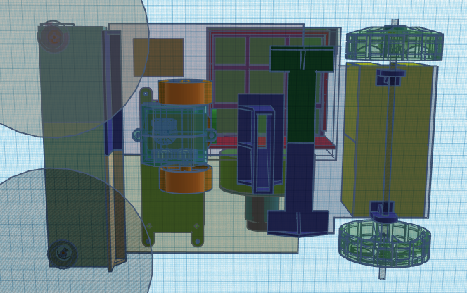
- Batteries and dust compartment should swap places. A less obvious move, it is due to the fact that batteries is the heaviest part of a device, and as they are on top of the rear wheels, the front wheels are not loaded enough, so the friction between them and the floor is insufficient.
- Sucker (the entry hole of a pipe, one we positioned just above the ground) should be located in front of the front wheels. This one is a killer, and if some brave engineer decides to fix the design, we expect a lot of curses here. See, we can not move front wheels back, as the design requires them in front. We also can not move brushes forward, as they are already. We can not move the sucker forward, as there is no place for it between brushes and front wheels. Yet…
Yet, if we leave things as they are now, the brushes are going to collect dust on the middle line, and front wheels will run over it before a sucker had a chance to remove it. Think dog's hair, getting stuck to the wheels.
So we need to suck in the dust, in front of the front wheels… somehow. As the point where dust is collected on a middle line is right between motors of brushes, there IS the place for a sucker, it is just a mater of design.
Fixators. We need to make sure a customer can pick the device, turn it over and so on. Right now accumulators are placed in the holder, but not fixed there, if device is tirned over, they will fall out. A cover (p.1) should do the job, just keep it in mind.
In this article we went over building a simple bump-and-run platform, intended as a vacuum cleaner or simply as a toy. In our next articles, we are going to build more complex machines with more complex behaviour and functions.
Good luck :)

