Three-valued Logic
List of accomplishments
- Basic ternary logic gates: T_NOT, T_OR, T_AND, T_NAND, T_NOR, T_XOR and more
- Synthesis, Minimization and Realization for Ternary Functions
- Ternary half adder, Ternary full adder, Ternary ripple carry adder
- Ternary full subtractor, comparator, multiplier, multiplexer/demultiplexer
- Ternary flip flap flops and latches
- A primitive Ternary Arithmetic and Logical Unit (ALU)
Conventions and used technologies
- Unbalanced Ternary (0, 1, 2) was used in implementation
- 1 Trit is expressed by 2 Bits: 0 ~ 00, 1 ~ 01, 2 ~10 (11 is undefined)
- ModelSim, Quartus prime, Logisim
Introduction
As first-year students of Innopolis University, we had the opportunity to realize projects throughout our computer architecture course. Our group was particularly interested in the ternary system and its functioning, so we decided to implement a simple ternary system with basic components (gates).
In logic, a three-valued logic (also trinary logic, trivalent, ternary) is one of several many-valued logic systems in which there are three truth values indicating true, false and some indeterminate third value.
Ternary logic is MVL (Multi-valued logic) compliant. However, only three logic states are used, '0','1' and '2'. The optimum radix (r) of a fractional number is found to be the natural logarithm (e). Ternary logic uses number representation with r=3, compared to binary logic which uses r=2, hence the most economical integer radix which is the closest to the natural logarithm e, is base 3. This special property of base 3 inspired the early computer designers to build a ternary computer.
The first working ternary computer was built in Russia at the Moscow State University in 1958. The computer was designed by Nikolay Brusentsov and his colleagues. They named it Setun, like the river that flows near the university campus.
Ternary Logic
A ternary logic function is a mapping F: {0,1,2}n -> {0,1,2}. We will discuss the advantages and disadvantages of ternary logic over binary logic.
Where Boolean logic has 22 = 4 unary operators, the addition of a third value in ternary logic leads to a total of 33 = 27 distinct operators on a single input value. Similarly, where Boolean logic has 222 = 16 distinct binary operators (operators with 2 inputs), ternary logic has 332= 19,683 such operators. Where we can easily name a significant fraction of the Boolean operators (not, and, or, nand, nor, exclusive or, equivalence, implication), it is unreasonable to attempt to name all but a small fraction of the possible ternary operators.
Advantages of Ternary Logic
A ternary logic representation enables a more compact and efficient information encoding than the equivalent binary logic representation. The argument stated is as follows: if we assume that a digital circuit has N possible input combinations, then a binary circuit requires log2N input lines and a ternary circuit requires log3N input lines.


Therefore, a ternary encoded realization of a given binary logic function should require 0.63 times the input lines than the corresponding binary realization.
Disadvantages of Ternary Logic
Although ternary logic circuits should require fewer input lines than the equivalent binary logic circuits, ternary logic circuits are currently not a practical choice. The reasons are
- Ternary hardware implementation technology is still in the theoretical, simulation, and laboratory test levels
- Representing three ternary logic levels (0, 1, and 2) using voltage levels of existing technology is not yet effectively defined
- No computational model and programming language is developed. However, simulating results of ternary circuit implementation using complementary metal oxide semiconductor (CMOS), resonant tunneling diode (RTD), and carbon nano-tube technologies, demonstrating that ternary logic may be a choice for future computing.
Various possible representations for the ternary system
- Ternary numeral system (Unbalanced ternary), each digit is a trit (trinary digit) having a value of: 0, 1, or 2
- Balanced ternary, each digit has one of 3 values: ?1, 0, or +1; these values may also be simplified to ?, 0, +, respectively (most commonly used)
- Redundant binary representation, each digit can have a value of ?1, 0, 0/1 (the value 0/1 has two different representations)
- Skew binary number system, only most-significant non-zero digit has a value 2, and the remaining digits have a value of 0 or 1
More about the balanced Ternary Numbering System
Today, mostly all hardware is designed for binary computing. If we had a stable electronic component with three stable states, the world perhaps would have turned to ternary computing. However, this is not the truth today. The balanced ternary radix notation has some beneficial properties:
- Ternary inversion is easy, just exchange ?1 with 1 and vice versa. If we use an example, 24 is represented as 1T0, and -24 as T10 in balanced ternary notation (T is simply a notation for -1). This is simpler than the rule for the two’s complement in binary logic.
- The sign of a number is given by its most significant nonzero ’trit’
- The operation of rounding to the nearest integer is identical to truncation.
- Addition and subtraction are essentially the same operation (I.e. you merely add the digits using the rules for addition of digits)
Examples:
2110 = 1T103; 29610 = 11T00T3;
-2410 = T103; -13710 = T110T13
Ternary Arithmetics
Ternary arithmetic can offer a more compact notation than binary arithmetic, and would have been an obvious choice if the hardware manufacturers would have found a ternary switch.
Balanced Ternary Addition and Multiplication
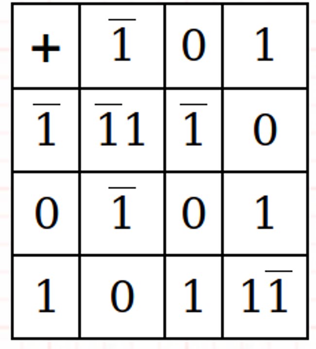
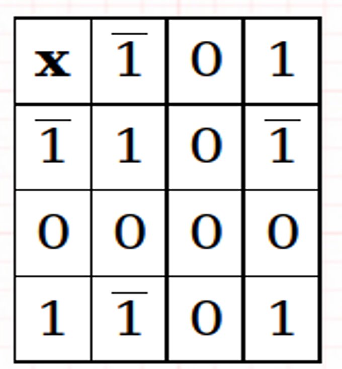
Examples:
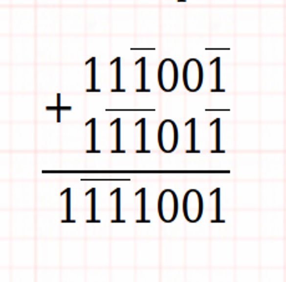
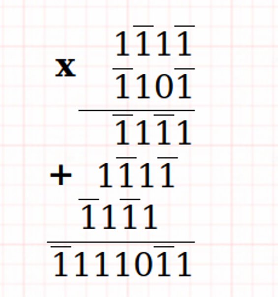
Ternary combinational circuits (Ternary gates)
A combinational circuit consists of input variables, ternary logic gates and output variables. The output of the circuit depends only upon the present input. Logic gates accept signals from the input variables and generate output signals. This process transforms ternary information from
the given input data to the required ternary output data.
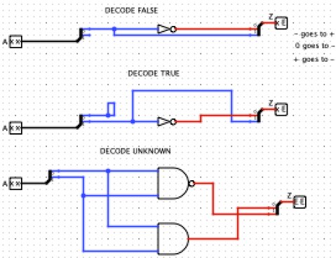
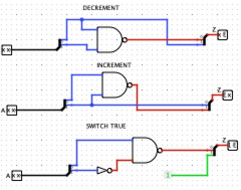
As mentioned above we can easily name a significant fraction of the Boolean operators (not, and, or, nand, nor, exclusive or, equivalence, implication), however, it is unreasonable to attempt to name all but a small fraction of the possible ternary operators. We will consider the following ternary circuits:
And (Min): It is natural to extend the Boolean and function to a ternary function by declaring that the result is true only if both inputs are true, false if any input is false, and unknown otherwise.
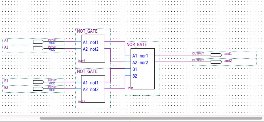
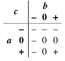
Or (Max): It is also natural to extend the Boolean or function to ternary by declaring that the result is true if any input is true, false only if both inputs are false, and unknown otherwise.
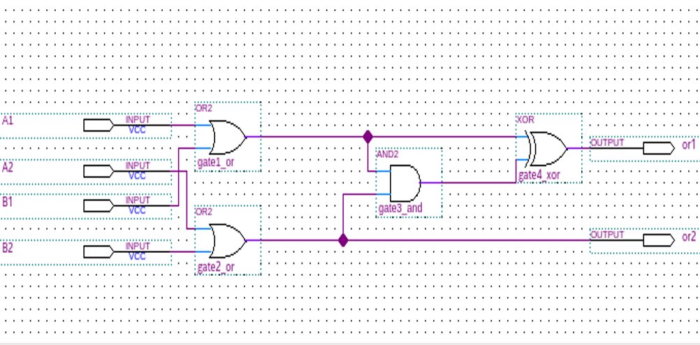
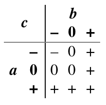
Consensus: In Boolean logic, the inverse of exclusive or is true when the two inputs are the same, and false when they are different. There are several natural extensions of this idea to ternary logic. One of them is the logical consensus of a set of variables, which is true if all are true, false if all are false, and otherwise unknown
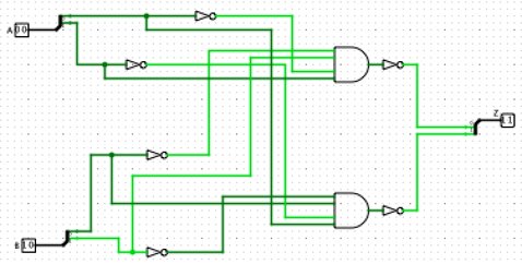
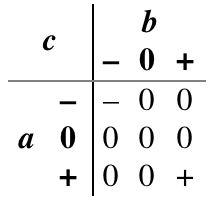
Any: Where consensus requires that both inputs agree before it asserts anything but unknown, the accept anything operator declares an unknown conclusion only if both inputs are unknown or actively disagree. Otherwise, it jumps to a conclusion from any non-unknown input available to it.
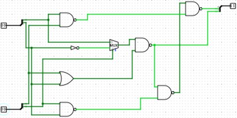
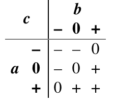
Increment and Decrement: In Boolean logic, the inverter may be thought of as incrementing or decrementing its argument modulo 2. In ternary logic, the modulo 3 increment and decrement functions are quite distinct from inversion.
Synthesis, Minimization and Realization for Ternary Functions
Relationships interrelated in the ternary logic system
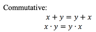


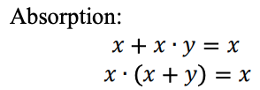
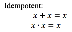
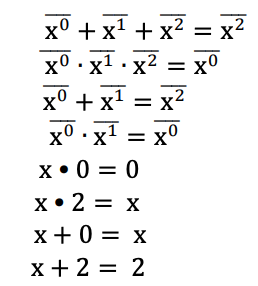
A ternary logic function can be represented as a Max-Min expression. Ternary Max-Min expressions are defined as follows:
Variable: Any symbol that takes value from the set T ? {0,1,2} is a ternary variable.
Literal: Literals are transformed forms of a variable. They are used to form Max-Min expressions.
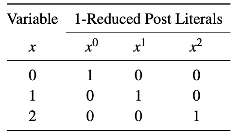
In the literature two types of literals are commonly used: 1-reduced Post literals and 2-reduced post literals. A 1-reduced Post literal of a variable x is represented as xi, where i ? {0,1,2}. When x = i, then xi = 1, otherwise xi = 0. The 1-reduced Post literals of a variable is shown below.
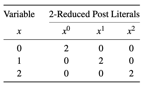
A 2-reduced Post literal of a variable x is represented as xi, where i ? {0,1,2}. When x = i, then xi = 2, otherwise xi = 0. The 2-reduced Post literals of a variable is shown below. This example makes use of different sets of literals to form Max-Min expressions as discussed previously.
Minterm: When literals of variables of a function are combined using the Min operation, then the term is called a minterm. For example, for a 3-variable ternary logic function F(x,y,z), xyz and xz are two examples of minterms.
Max-Min Expression: When two or more minterms are combined using Max operations, then the expression is called a Max of minterms (Max-Min) expression. For example, for a 3-variable ternary logic function F(x,y,z) = xy + yz + xyz is an example of a Max-Min expression.
Any function F(x,y,z) can always be represented as

Three basic methods to minimize ternary functions are:
- Manipulation of algebra expression as in Boolean algebra.
- The tabular method.
- Ternary K. map method.
For the implementation of ternary circuits it is necessary to convert ternary variable into unary variable (using the 2-Reduced Post Literals table).
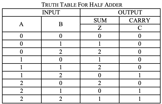
Ternary half adder
A circuit for the addition two 1 trit numbers is referred to as a half adder. the circuit does not consider a carry generated in the previous addition. The addition process in ternary logic system is shown below. Here A and B are two inputs and sum(S) and carry (CARRY)
are two outputs.
Analysis
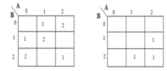
A karnaugh map (K-map) is used to represent the sum and carry output. K-maps are useful for minimization and optimization of logic circuits. Here a K-map of 2 inputs is used. Since no grouping of 2’s and 1’is possible, the output equation is as below.

Implementation
module half_adder (
    input [1:0] A, [1:0] B,
    output [1:0] sum, [1:0] carry

);

wire [1:0] temp = 2'b01;
wire [1:0] a0, a1, a2, b0, b1, b2;
wire [1:0] i0, i1, i2, i3, i4, i5;
wire [1:0] o0, o1, o2, o3, o4;
wire [1:0] c0, c1, c2, c3;

mask msk_1(A, a0, a1, a2);
mask msk_2(B, b0, b1, b2);

andgate and_1(a2,b0,i0);
andgate and_2(a1,b1,i1);
andgate and_3(a0,b2,i2); // partial products

orgate or_1(i0, i1, o0);
orgate or_2(o0, i2, o1); // f1

andgate and_4(a1,b0,i3);
andgate and_5(a0,b1,i4);
andgate and_6(a2,b2,i5); // partial products

orgate or_3(i3, i4, o2);
orgate or_4(o2, i5, o3); // f2
andgate and_7(o3,temp,o4); // 1.f2

andgate andc_0(a2,b1,c0);
andgate andc_1(a1,b2,c1);
orgate orc_0(c0,c1,c2);
orgate orc_1(c2,i5,c3);
andgate andc_2(c3,temp,carry); // carry
orgate or_5(o1, o4, sum); // sum
endmodule
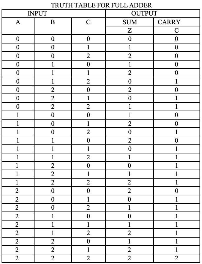
Ternary full adder
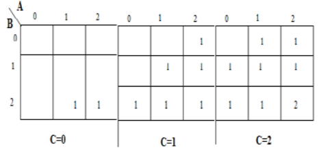
As with half adders, one stage of a ternary full adder can be described by a numerical table giving the sum SUM and carry out CARRY as a function of the three inputs A, B, along with the carry in C:
Analysis
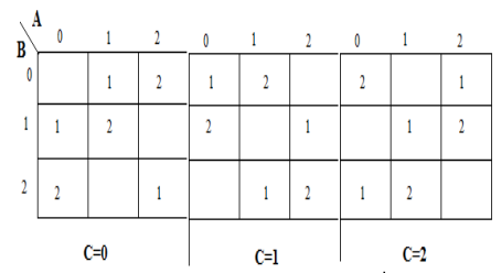
A karnaugh map (K-map) is used to represent the sum and carry output. K-maps are useful for minimization and optimization of logic circuits. Here a K-map of 3 inputs is used.


Implementation
module ternary_full_adder (
    input [1:0] A, [1:0] B, [1:0] c_in,
    output [1:0] sum, [1:0] c_out

);
wire [1:0] temp1 = 2'b01;
wire [1:0] temp2 = 2'b00;
wire [1:0] a0, a1, a2, b0, b1, b2, a20;
wire [1:0] i0, i1, i2, i3, i4;
wire [1:0] i5, i6, i7, i8, i9, i10, i11, i12, i13, i14, i15, i16, i17;
wire [1:0] o0, o1, o2, o3, o4, o5, o6, o7, o8, o9;
wire [1:0] c0, c1, c2;
wire [1:0] h0, h1, h2, h3, h4, h5, h6, h7;
wire [1:0] t0, t1, t2, t3, t4, t5, t6, t7, t8, t9, t10, t11, t12, t13, t14, t15, t16;
wire [1:0] g0, g1, g2, g3, g4, g5, g6, g7, g8, g9, g10, g11, g12, g13, g14, g15;

mask mk_1(A, a0, a1, a2);
mask mk_2(B, b0, b1, b2);
mask mk_3(c_in, c0, c1, c2);

andgate3 and3_1(a2,b0,c0, i0);
andgate3 and3_2(a1,b0,c1, i1);
andgate3 and3_3(a0,b0,c2, i2);
andgate3 and3_4(a1,b1,c0, i3);
andgate3 and3_5(a0,b1,c1, i4);
andgate3 and3_6(a2,b1,c2, i5);
andgate3 and3_7(a0,b2,c0, i6);
andgate3 and3_8(a2,b2,c1, i7);
andgate3 and3_9(a1,b2,c2, i8);

andgate3 and3_10(a1,b0,c0, i9);
andgate3 and3_11(a0,b0,c1, i10);
orgate or__(a2, a0, a20);
andgate3 and3_12(a20,b0,c2, i11); // note a20
andgate3 and3_13(a0,b1,c0, i12);
andgate3 and3_14(a2,b1,c1, i13);
andgate3 and3_15(a1,B,c2, i14);
andgate3 and3_16(a2,b2,c0, i15);
andgate3 and3_17(a1,b2,c1, i16);
andgate3 and3_18(temp2,b2,c2, i17);

orgate or_1(i9, i10, o0);
orgate or_2(o0, i11, o1);
orgate or_3(o1, i12, o2);
orgate or_4(o2, i13, o3);
orgate or_5(o3, i14, o4);
orgate or_6(o4, i15, o5);
orgate or_7(o5, i16, o6);
orgate or_8(o6, i17, o7);

andgate and_1(o7, temp1, o8); // 1.f2
orgate or_9(i0, i1, h0);
orgate or_10(h0, i2, h1);
orgate or_11(h1, i3, h2);
orgate or_12(h2, i4, h3);
orgate or_13(h3, i5, h4);
orgate or_14(h4, i6, h5);
orgate or_15(h5, i7, h6);
orgate or_16(h6, i8, h7);
orgate or_17_(h7, o8, sum); // sum
// carry
andgate3 and3_19(a2,b2,c2, t0); // f1
andgate3 and3_20(a0,b1,c2, t1);
andgate3 and3_21(a0,b2,c2, t2);
andgate3 and3_22(a0,b2,c1, t3);
andgate3 and3_23(a1,b2,c0, t4);
andgate3 and3_24(a2,b2,c0, t5);
andgate3 and3_25(a1,b1,c1, t6);
andgate3 and3_26(a1,b2,c1, t7);
andgate3 and3_27(a1,b0,c2, t8);
andgate3 and3_28(a1,b1,c2, t9);
andgate3 and3_29(a1,b2,c2, t10);
andgate3 and3_25_(a2,b0,c2, t11);
andgate3 and3_26_(a2,b1,c2, t12);
andgate3 and3_27_(a2,b0,c1, t13);
andgate3 and3_28_(a2,b1,c1, t14);
andgate3 and3_29_(a2,b2,c1, t15);
andgate3 and3_9_(a2,b1,c0, t16);
orgate or_17(t1, t2, g0);
orgate or_18(g0, t3, g1);
orgate or_19(g1, t4, g2);
orgate or_20(g2, t5, g3);
orgate or_21(g3, t6, g4);
orgate or_22(g4, t7, g5);
orgate or_23(g5, t8, g6);
orgate or_24(g6, t9, g7);
orgate or_25(g7, t10, g8);
orgate or_21_(g8, t11, g9);
orgate or_22_(g9, t12, g10);
orgate or_23_(g10, t13, g11);
orgate or_24_(g11, t14, g12);
orgate or_25_(g12, t15, g13);
orgate or_5_(g13, t16, g14); //f2
andgate and_2(g14, temp1, g15); // 1.f2
orgate or_26(g15, t0, c_out); // carry
endmodule
Ternary Full Subtractor
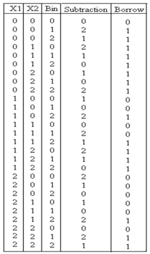
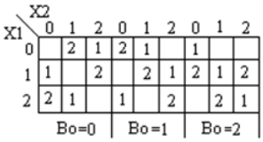
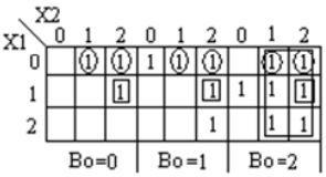
Ternary full-Subtractor is a circuit that subtracts two inputs and previous borrow. Truth table for Subtractor is shown below


module full_subtractor(
    input [1:0] P, Q, b_in,
    output [1:0] diff, b_out
);

wire [1:0] temp1 = 2'b01;
wire [1:0] temp2 = 2'b10;
wire [1:0] a0, a1, a2, b0, b1, b2;
wire [1:0] i0, i1, i2, i3, i4, i5, i6, i7, i8, i9, i10, i11, i12, i13, i14, i15, i16, i17;
wire [1:0] c0, c1, c2, c3;
wire [1:0] h0, h1, h2, h3, h4, h5, h6, h7, h8, h9, h10, h11;
wire [1:0] t0, t1, t2, t3, t4, t5, t6, t7, t8, t9;

wire [1:0] p0, p1, p2;
wire [1:0] q0, q1, q2;

mask mk_1(P, p0, p1, p2);
mask mk_2(Q, q0, q1, q2);
mask mk_3(b_in, b0, b1, b2);

andgate and_0(p0, q1, i0);
andgate3 and3_0(p2, p1, q2, i1);
orgate or_0(i0, i1, i2);
andgate and_1(b0, i2, i3); // first expression

andgate and_2(p0, q0, i4);
andgate and_3(p1, q1, i5);
andgate and_4(p2, q2, i6);
orgate or_1(i4, i5, i7);
orgate or_2(i7, i6, i8);
andgate and_5(i8, b1, i9); // second expression

andgate and_6(p1, q0, i10);
andgate and_7(p0, q2, i11);
andgate and_8(p2, q1, i12);
orgate or_3(i10, i11, i13);
orgate or_4(i13, i12, i14);
andgate and_9(i14, b2, i15); // third expression

orgate or_5(i3, i9, i16);
orgate or_6(i16, i15, c0); //f1

orgate or_7(i10, i12, t0);
orgate or_8(t0, i11, t1);
andgate and_10(t1, b0, t2); // 1 expression

andgate and_11(p1, q2, i17);
orgate or_9(i4, i17, t3);
andgate and_12(t3, b1, t4); // 1- expression

orgate or_10(i4, i5, t5);
orgate or_11(t5, i6, t6);
andgate and_12_(t6, b2, t7); // 1-- expression

orgate or_12(t2, t4, t8);
orgate or_13(t8, t7, t9);
andgate and_13(t9, temp1, c1);

orgate or_14(c0, c1, diff); // difference

orgate or_15(q1, q2, h0);
andgate and_14(h0, temp2, h1);
andgate and_15(h1, b2, h3); // 1 b

orgate or_16(i0, i11, h4);
andgate and_16(h4, temp2, h5); // 1- b

andgate and_17(i17, temp2, h6); // 1-- b

andgate3 and3_1(p2, q2, b1, h7); // 1--- b
andgate3 and3_2(p1, q0, b2, h8); // 1---- b

orgate or_17(h3, h5, h9);
orgate or_18(h9, h6, h10);
orgate or_19(h10, h7, h11);
orgate or_20(h11, h8, b_out); // borrow
endmodule
Ternary Ripple Carry Adder
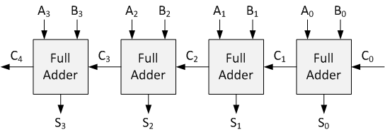
Ripple-carry adder(RCA) is a well-known circuit for performing addition of two numbers by cascading ternary full adders. A Ternary RCA is quite similar to its Binary counterpart. A Ternary Half Adder is employed to add the least signi?cant Ternary digits. The rest are summed up by Ternary Full Adders. As mentioned before, Ternary Full Adder adds three Ternary input variables.
Implementation
module ternary_ripple_adder (
    input [15:0] input1 ,
    input [15:0] input2 ,
    output [15:0] out ,
    output [1:0] overflow_trit
);

wire [15:0] carry ;
reg tem;

assign carry[0] = tem;
assign carry[1] = tem;

always @(input1, input2)
begin
    tem <= 1'b0;
end

generate
  genvar i;
  for (i = 0; i <= 12; i=i+2)
    begin
    full_add af({input1[i+1],input1[i]}, {input2[i+1],input2[i]},
        {carry[i+1],carry[i]}, {out[i+1], out[i]}, {carry[i+3],carry[i+2]});
    end
    full_add af({input1[15],input1[14]}, {input2[15],input2[14]},
    {carry[15],carry[14]}, {out[15], out[14]}, overflow_trit);
endgenerate
endmodule
Ternary Comparators
Ternary comparator circuit camper two inputs X1, X2 and accordingly generates output as X1 = X2, X1 > X2, X1 < X2. Truth table for a ternary comparator is shown below
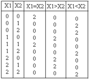
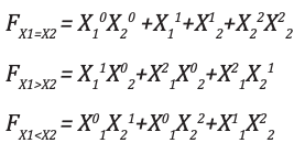
Output equation for X1 = X2, X1 > X2, X1 < X2 are:
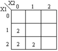
Corresponding k-maps are shown below

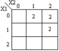
module ternary_comparators (
    input [1:0] x1, x2,
    output [1:0] f1, f2, f3
);
wire [1:0] t0, t1, t2, t3, t4, t5, t6, t7;
wire [1:0] h0, h1, h2, h3, h4, h5;
wire [1:0] x10, x11, x12;
wire [1:0] x20, x21, x22;

mask mk_1(x1, x10, x11, x12);
mask mk_2(x2, x20, x21, x22);

andgate and_0(x10, x20, t0);
andgate and_1(x22, x22, t1);
orgate or_0(t0, t1, h0);
orgate or_1(h0, x11, h1);
orgate or_2(h1, x21, f1); // x1 == x2

andgate and_2(x11, x20, t2);
andgate and_3(x12, x20, t3);
andgate and_4(x12, x21, t4);
orgate or_3(t2, t3, h3);
orgate or_4(h3, t4, f2); // x1>x2

andgate and_5(x10, x21, t5);
andgate and_6(x10, x22, t6);
andgate and_7(x11, x22, t7);
orgate or_5(t5, t6, h4);
orgate or_6(h4, t7, f3); // x1<X2
endmodule
Ternary Multiplier
Ternary multiplier is a circuit that multiplies two input numbers and generates corresponding product. Truth table for this circuit is shown below:
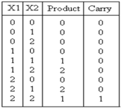
The resulting expression for the product and carry are shown:

The corresponding K-maps are shown:
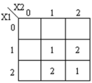
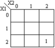
module ternary_multiplier (
    input [1:0] A, [1:0] B,
    output [1:0] product, [1:0] carry

);

wire [1:0] temp = 2'b01;
wire [1:0] a0, a1, a2, b0, b1, b2;
wire [1:0] i0, i1, i2, i3, i4, i5;
wire [1:0] o0, o1, o2, o3, o4;

mask msk_1(A, a0, a1, a2);
mask msk_2(B, b0, b1, b2);

andgate and_1(a1,b2,i0);
andgate and_2(a2,b1,i1);
orgate or_1(i0, i1, o0); // f1

andgate and_4(a1,b1,i3);
andgate and_5(a2,b2,i4);
orgate or_3(i3, i4, o2);
andgate and_3(temp,o2,o3);
orgate or_4(o3, o0, product); // product

andgate andc_0(a2,b2,o4);
andgate andc_1(temp,o4,carry); // carry

endmodule
Ternary Multiplexers and Demultiplexers
Multiplexer is a circuit having multiple inputs and a single output. It is also known as decoder. The output function of the multiplexer is determined by the number of function lines. Thus for 2 trit
multiplexer the output will be 32 = 9 and two will be the function select lines. Multiplexer i.e. function
selection logic selects 1 out of 9 functions as an output. Function select logic is implemented using logic gates. The output equation of function selection logic is:

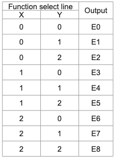
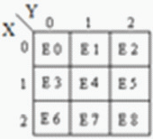
Demultiplexer is also referred to as encoder. Its functionality is reverse to that of multiplexer. It accepts the single input and distributes it over several outputs
Simple Ternary D Latch
Although design of circuits implementing combinational ternary logic is straightforward, the design of a simple and robust ternary memory element (i.e latch) suitable for integrated circuit (IC) implementation has been challenging. However, a simple ternary latch can be obtained by replacing the binary NOR or NAND gates used with corresponding ternary T_NOR or T_NAND gates.
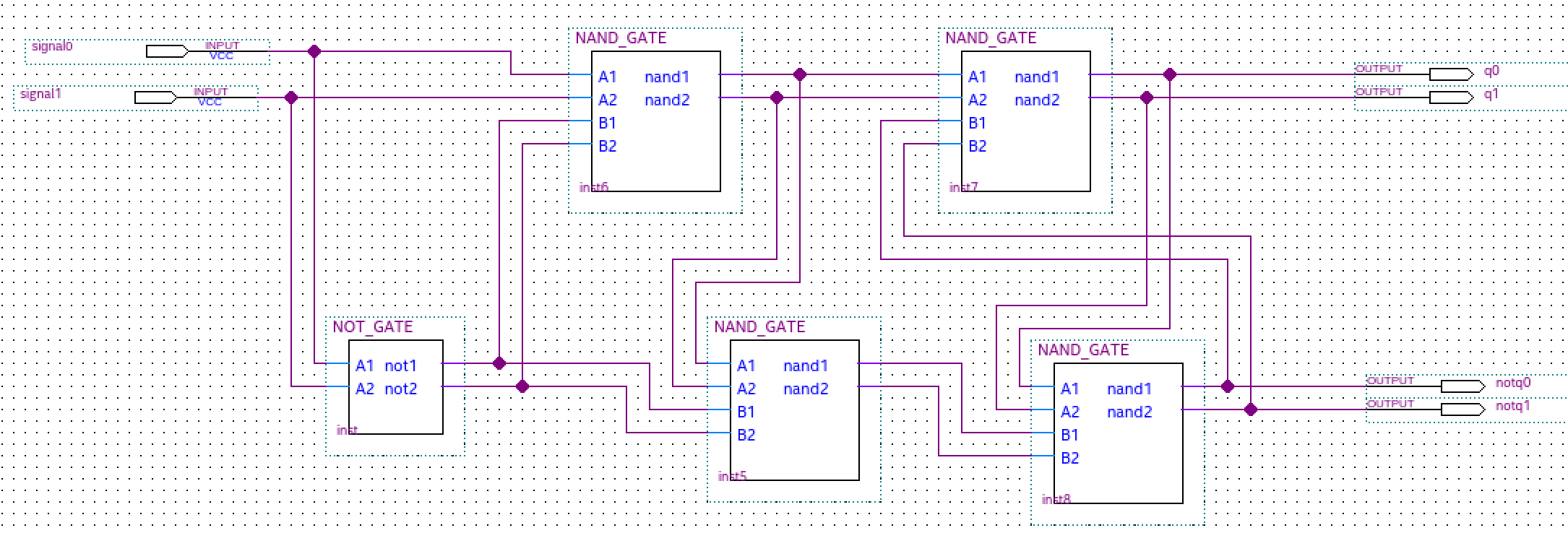
Simple Ternary D Flip-Flap-Flop
The Master Slave (MS) ternary D Flip-Flap-Flop (FFF) is realized based on the ternary D latches. This is similar to the way the binary D Flip-Flop (FF) is realized using binary D latches. The logic diagram and the operation description of the MS binary D flip-flop are well known. In order to implement the MS ternary D FFF, we replace the binary D latches with ternary D latches (realized with ternary negated-minimun gates of two inputs – NAND) and the binary inverters with simple ternary inverters (STI). The truth tables for both the ternary NAND circuits and ternary STI circuits are shown

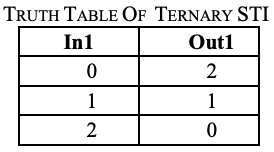
For MS ternary D FFF with binary clock, the data are ternary (0, 1 and 2 logic) and the clock is binary (low and high – in our
implementation, 0 and 2 logic). The MS ternary D FFF with
binary clock can read the data when the clock goes from low to
high (positive edge) or from high to low (negative edge), depending
on the number of STIs.
The inputs of the ternary D FFF are Data and Clk, and the outputs are Q and Not_Q. The clock signal is binary and the logic levels are denoted 0 and 2, in order to maintain the correspondence with electrical implementation


1-bit Ternary Arithmetic and Logic Unit (T-ALU)
Ternary Arithmetic Logic Unit (ALU) is a digital circuit used to perform arithmetic and logic operations. It represents the fundamental building block of the Central Processing Unit (CPU) of a ternary computer. ALU carries out arithmetic operations like addition, subtraction, multiplication, and logic operations compare, NAND, NOR, NOT, AND, and OR. Below is shown a primitive architecture of a 1 trit ALU
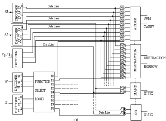
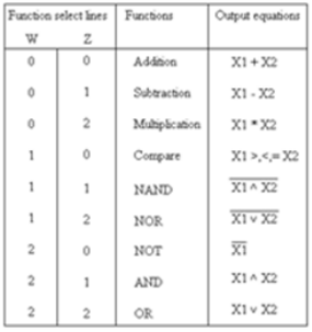

Basic building blocks of ALU are decoders, function select logic (Multiplexer), transmission gate and separate processing modules. Function selection logic selects 1 out of 9 functions listed depending upon the logic state on function select lines W and Z.
Output lines of selection logic are connected to TG (Ternary gate) associated with each module. Any module is selected only when associated TG is enabled else it is isolated from data lines. For e.g. If input from select lines W and Z = 0, output E0 of selection logic is high (2) while E1, to E8 is low (0) so, TG associated with adder module will be enable allowing data
lines to be connected to adder modules while other modules are isolated from the data lines.
Finally, by cascading n/2 trit ALU slices, an n trit ALU can be formed.
Комментарии (10)

andy_p
01.12.2018 17:32> 1 Trit is expressed by 2 Bits: 0 ~ 00, 1 ~ 01, 2 ~10 (11 is undefined)
Уж лучше использовать истинно троичные элементы на мультиплексорах.

funca
02.12.2018 01:15Говорят, что индейцы Аймара используют троичную логику как основную в системе понятий, что нашло отражение в их языке. Да, нет и не знаю. Закон исключения третьего для них не работает. На уровне софта тоже используется довольно часто. Например в SQL: true, false и null.

tchspprt
02.12.2018 11:04Технически, null — это не состояние. Это — отсутствие сигнала. Вот тут описан пример того, как это реализуется в наших текущих двоичнологичных машинах — habr.com/post/431010 (возможно, не самый достоверный пример и автор мог ошибаться со своими расчётами, но то, что процесс обновления есть, и то, что он есть тот же самый null — неоспоримо). Превращаются ли от этого наши машины (или хотя бы частное — память наших машин) в троичнологичные? Сомнительно.
И троичная логика не лишается способности null. Превращается ли она от этого в четверичную? Сомнительно, опять же.
То, что в некоторых отдельных случаях некоторые отдельные инженеры используют null как состояние, которое имеет положительную нагрузку и смысл наравне с true и false не означает что null для этого придуман, полагаю.

KvanTTT
02.12.2018 13:25Why didn't you write about universal function (Webb function) that can express others?
Inc(x) = W(x, x)
Dec(x) = Inc(Inc(x))
~x = W(W(Dec(x), Inc(x)), Inc(W(Dec(x), x))
x & y = ~(~x | ~y)
x | y = Inc(Inc(W(x, y))
There is a big disadvantage of ternary logic comapre to the binary one. Compare functions above with the following ones:
~x = W(x, x)
x & y = ~(~x | ~y) = W(W(x, x), W(y, y))
x | y = Inc(W(x, y)) = W(W(x, y), W(x, y))
Ternary logic has much more operations for "logical and" (22
Wops versus 3).
Also, see my question about Inverse function in multi-valued logic through the Webb function on math.stackexchange.com.


kinall
Если продолжить это рассуждение, то почему бы не перейти далее к четверичной, пятиричной и так далее системам?
PS Или к англоязычным статьям принято оставлять комментарии на английском? Не уверен в своём знании этой части сетевого этикета)
pacaya
В статье есть ответ:
Обоснование этого утверждения можно легко найти. В качестве примера: http://phg.su/basis2/X51.HTM, или https://en.wikipedia.org/wiki/Radix_economy
kinall
А, прошу прощения, проглядел. Спасибо!
tchspprt
Говоря языком статьи — «more compact» стоит между двоичной и троичной системами счисления. Вот почему: habr.com/post/427969
Плюс ко всему нужно кардинально перестраивать всё на уровне электронных компонентов, потому что изменится шаг и нужно более точно учиться разделять двойку, единицу и нуль уже в троичной системе и всё будет ещё сложнее в дальнейшем.
kinall
Насколько я понимаю, аппаратные сложности — это вообще основная проблема троичной логики. И только после неё — проблема (не)совместимости с двоичной.
Fandir
Мне в универе чуть ли не на первых лекциях связанных со схемотехникой и архитектурой сразу объяснили, что типа троичная система более эффективна, но сложнее в реализации в СССР кстати троичную логику активно рассматривали, да и сейчас тоже иногда вспоминают… Пару лет назад даже видел защиту диплома, где студент разработал и смоделировал в Мультисим некоторые троичные элементы…