Boundary representation (B-rep) is the primary method of representing modeled objects in most geometric kernels, including our C3D Modeler kernel. The core algorithms that edit models, such as applying fillet operations, performing cutting operations, and obtaining flat projections require the precision of B-rep representations. The rapidly growing variety of 3D data in polygonal formats makes the task of model transformations from polygons into boundary representation increasingly relevant. As a result, we developed a new SDK, C3D B-Shaper, which is part of our C3D Toolkit.
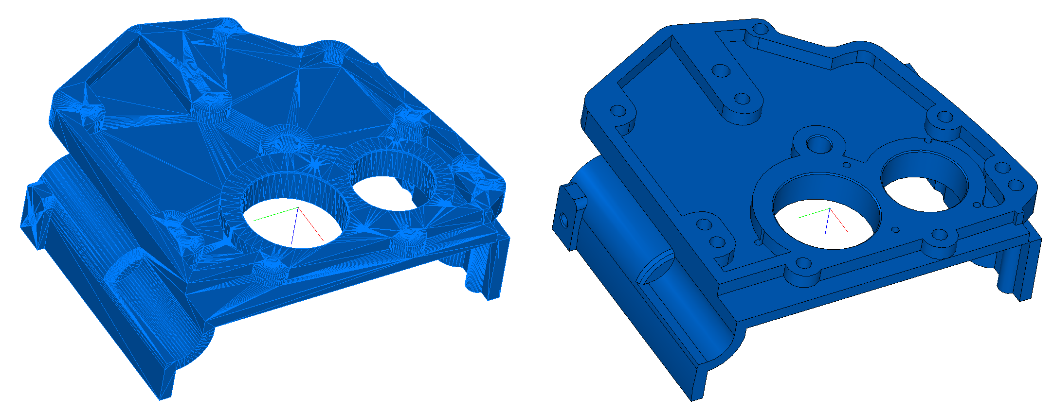
Using a triangulation algorithm (known as tessellization) on a model's boundary representation is relatively easy. Building polygonal (tessellated) representations is useful for visualization purposes and for doing geometric calculations.
The reverse transformation — from the polygonal representation to B-rep — faces, however, a series of issues related to the complexity in recognizing different types of surfaces, including free-form ones. As well, there is the problem of noise in polygonal models that appear typically as the result of 3D scanning.
The general process by which C3D B-Shaper transforms models from polygonal to B-rep formats consists of three stages: segmentation, reconstruction of surfaces, and b-rep model construction. The transformation process is iterative: if users are for any reason unhappy with the results, then corrections can be made during the segmentation and surface reconstruction stages.

Transforming a polygonal representation into a B-rep
Before initiating the process of b-rep transformation, however, we improve the quality of the source polygonal mesh by applying the following fixes: coordinate the directions of normals in adjacent polygons; eliminate holes; and apply smoothing algorithms to noisy mesh sources, if any.
The first stage of transformation is segmenting the polygonal model. We classify the mesh polygon into subsets (segments). Information about the normals at each mesh vertex makes it possible to perform a first-order segmentation and then carry out the initial mesh splitting, as well as classify areas as flat or highly curved. The initial mesh splitting is based on defining «sharp» edges. These are the edges between two triangular polygons where the angle between their average normals exceeds a predefined value.
A second-order segmentation analyzes the mesh based on its main curvature, which is sufficient for classifying elementary surfaces. When calculating curvatures at mesh vertices, we use the results of Meyer's work (Mark Meyer, Mathieu Desbrun, Peter Schroder, and Alan H. Barr, «Discrete Differential-Geometry Operators for Triangulated 2-Manifolds,» Visualization and Mathematics III, 2003) in defining a discrete differential operator for triangulated regions: a set of adjacent vertices (related to a given vertex via an edge) is considered for each initial mesh vertex. Next, a discrete operator K is calculated for the vertex. Based on the operator, the average normal, mean KH, and Gaussian KG curvatures are defined at the mesh vertex.
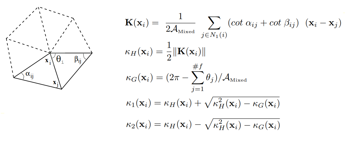
Defining discrete differential operators for triangulated regions
In this way the curvature tensor is calculated for each mesh vertex, from which the principal curvature values K1 and K2 and principal curvature directions are extracted.
Mesh vertices are classified by the values of their principal curvatures K1 and K2, and then are calculated for them. The vertex classification algorithm is based on k-means, i.e., minimizing the total squared deviation of cluster points from the centers of the clusters. The resulting output from the algorithm contains a mesh vertex associated with a cluster and a pair of curvatures (cluster-center — L. Guillaume, «Curvature Tensor Based Triangle Mesh Segmentation with Boundary Rectification,» Proceedings Computer Graphics International (CGI), 2004).
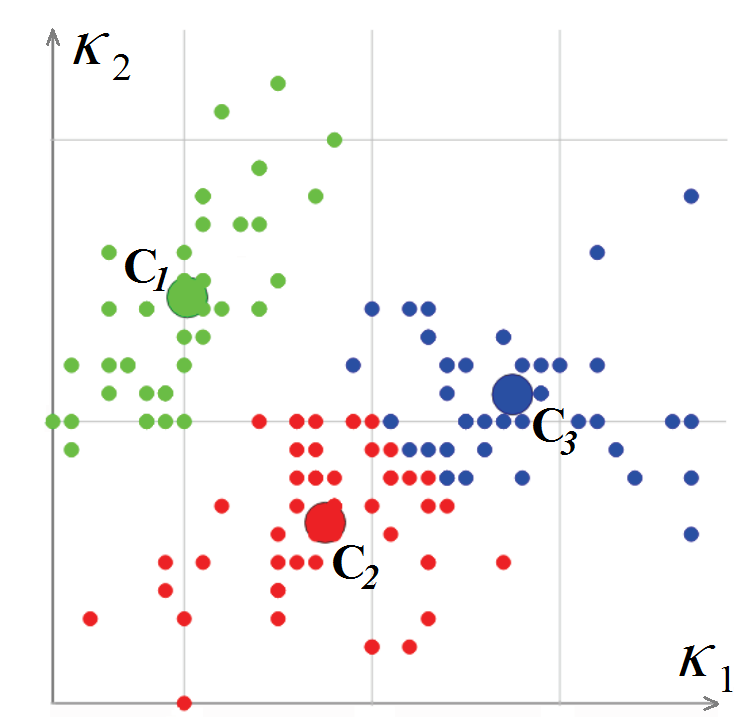
Classifying polygonal mesh vertices in the curvature space
Once we finish classifying the vertices of the polygonal mesh, we go on to classifying the polygons. To start this procedure, we choose a triangular polygon whose curvature may be considered fully defined. This is one whose three vertices are within a single cluster, or has two vertices on a sharp edge. The polygon is labeled as a new segment and becomes the starting point for a recursive procedure that expands the segment: for each triangular polygon, adjacent polygons are considered as long as the edge between them is not «sharp.» When an adjacent polygon vertex, which is opposite to a common edge, is on a sharp edge or belongs to the same cluster, the polygon is added to the segment. The process is repeated until all of the polygons making up the mesh gone.

Polygonal mesh segmentation
Once the segment-creation procedure is complete, another algorithm stitches adjacent segments together to eliminate the over-segmentation of the mesh.
The second stage is surface recognition. Each segment must be approximated by a surface with a precision determined by the system or by users.
Firstly, the principal curvature values of the segments are used to determine if it is at all possible to describe the segment’s form by one of the following elementary surfaces:
To create elementary surfaces, we fit simple geometric objects onto sets of points using the appropriate algorithm. For instance, to fit a circle and a sphere onto a set of points, the method of least squares is used; to fit a plane, the principal component analysis is used. The system ensures that each reconstructed surface is related to a segment within a predefined precision of recognition.
The figure below illustrates recognized surfaces by color: planes are shown in blue, cylinders are in red, spheres in green, cones yellow, and toroids violet.
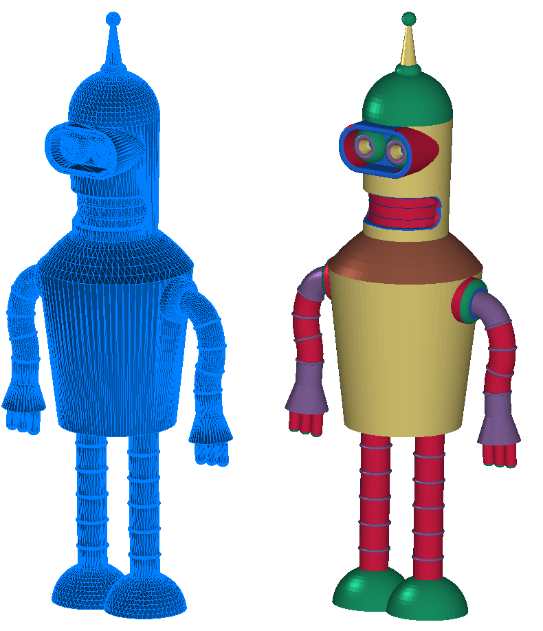
Source polygonal mesh (left) and segmented mesh (right) with recognized surface segments
If no elementary surface is able to describe the segment, then the system attempts to recognize an extrusion surface or a revolution surface.
When the system ultimately fails to find an analytical surface by which to describe the segment form, a NURBS surface is created for it.
The final stage of the transformation is to create the B-rep model based on the segmentation and reconstructed surface data. An adjacency graph is created from the segmented regions to represent the model’s topology, and forms the basis for creating the resulting B-rep model. B-rep models are assembled in a fully automatic mode, in contrast to the preceding stages:
It is, however, not always possible to create a shell with the correct topology. For instance, take two surfaces such as a cylinder and a plane that are nearly tangent to one other in space. Due to the tolerance specified for the reconstructed surfaces, they may not intersect at all. As a result, the created shell may have defects. Users can eliminate defects by correcting the surface parameters.
There are numerous sources of polygonal models available online:
Polygonal models from these sources can be divided into two groups: models that were triangulated (meshed) from B-rep objects, and all other models. A pair of features specific to the first group is the absence of polygonal mesh noise and the domination of analytical surfaces. This means that models from the first group can be easily transformed into b-reps in fully automated mode or with minimal user effort.
Polygonal meshes of models in the second group have noise, contain organic surfaces, and so they more likely require the interactive participation of users.
Thus we provide two modes for operating C3D B-Shape, fully automatic and interactive. Users can switch between recognition modes, and manage surface types during the reconstruction process. Selecting a mode can depend on the purpose of performing the transformation: users may sometimes want to disregard the topological connectivity of the resulting shell, or its overall correctness. This is often the case when optimizing displaying in BIM applications, in which users are adding custom interior elements to the architectural model.
On the other hand, reverse engineering tasks require the most accurate copy possible of the source models so that the resulting model has a correct topology. So, it is necessary to predefine the precision of, say, cylinders' co-axiality or the tangency of two surfaces. In these kinds of cases, the participation of users in the transformation process is crucial.
C3D B-Shaper’s automatic transformation employs the following functions that use as input data the source mesh and transformation settings:
One of the transformation settings is a recognition-precision value that sets the maximum tolerance for distances between segment vertices and recognized surfaces. The precision can be absolute or relative. When using relative precision, the deviations of faces from mesh bodies are measured relative to the model’s size.
The MbMeshProcessor interface class offers advanced options for managing the segmentation and recognition of surfaces:
To, for example, correct the results from automatic segmentation, C3D B-Shaper offers tools for merging and dividing segments, and so on. Users can fit surfaces of given types onto the selected segment, as well as modify the parameters of recognized surfaces.
The result of C3D B-Shaper’s transformation algorithms is illustrated by the figures below, in which a complex 3D model is successfully transformed from its polygonal mesh representation to a boundary-representation solid.

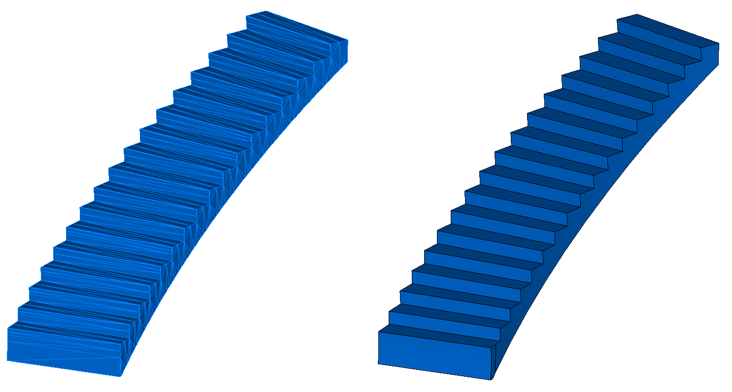
Polygonal mesh (left) and B-rep model (right) converted with C3D B-Shaper
Our aim is to create a powerful SDK for transforming models from polygonal to B-rep, and so development of C3D B-Shaper continues. Some of the things we are working on include advancing the automatic segmentation algorithms, developing tools for segmentation editing, improving the construction of free-form NURBS surfaces, and upping the quality of B-rep shell assemblies.
Customers who use the C3D geometric kernel are also a factor in driving the development of C3D B-Shaper.
Developers are welcome to test C3D B-Shaper as part of the C3D Toolkit or as a standalone component.

Using a triangulation algorithm (known as tessellization) on a model's boundary representation is relatively easy. Building polygonal (tessellated) representations is useful for visualization purposes and for doing geometric calculations.
The reverse transformation — from the polygonal representation to B-rep — faces, however, a series of issues related to the complexity in recognizing different types of surfaces, including free-form ones. As well, there is the problem of noise in polygonal models that appear typically as the result of 3D scanning.
The general process by which C3D B-Shaper transforms models from polygonal to B-rep formats consists of three stages: segmentation, reconstruction of surfaces, and b-rep model construction. The transformation process is iterative: if users are for any reason unhappy with the results, then corrections can be made during the segmentation and surface reconstruction stages.

Transforming a polygonal representation into a B-rep
Before initiating the process of b-rep transformation, however, we improve the quality of the source polygonal mesh by applying the following fixes: coordinate the directions of normals in adjacent polygons; eliminate holes; and apply smoothing algorithms to noisy mesh sources, if any.
Segmenting the Polygonal Model
The first stage of transformation is segmenting the polygonal model. We classify the mesh polygon into subsets (segments). Information about the normals at each mesh vertex makes it possible to perform a first-order segmentation and then carry out the initial mesh splitting, as well as classify areas as flat or highly curved. The initial mesh splitting is based on defining «sharp» edges. These are the edges between two triangular polygons where the angle between their average normals exceeds a predefined value.
A second-order segmentation analyzes the mesh based on its main curvature, which is sufficient for classifying elementary surfaces. When calculating curvatures at mesh vertices, we use the results of Meyer's work (Mark Meyer, Mathieu Desbrun, Peter Schroder, and Alan H. Barr, «Discrete Differential-Geometry Operators for Triangulated 2-Manifolds,» Visualization and Mathematics III, 2003) in defining a discrete differential operator for triangulated regions: a set of adjacent vertices (related to a given vertex via an edge) is considered for each initial mesh vertex. Next, a discrete operator K is calculated for the vertex. Based on the operator, the average normal, mean KH, and Gaussian KG curvatures are defined at the mesh vertex.

Defining discrete differential operators for triangulated regions
In this way the curvature tensor is calculated for each mesh vertex, from which the principal curvature values K1 and K2 and principal curvature directions are extracted.
Mesh vertices are classified by the values of their principal curvatures K1 and K2, and then are calculated for them. The vertex classification algorithm is based on k-means, i.e., minimizing the total squared deviation of cluster points from the centers of the clusters. The resulting output from the algorithm contains a mesh vertex associated with a cluster and a pair of curvatures (cluster-center — L. Guillaume, «Curvature Tensor Based Triangle Mesh Segmentation with Boundary Rectification,» Proceedings Computer Graphics International (CGI), 2004).

Classifying polygonal mesh vertices in the curvature space
Once we finish classifying the vertices of the polygonal mesh, we go on to classifying the polygons. To start this procedure, we choose a triangular polygon whose curvature may be considered fully defined. This is one whose three vertices are within a single cluster, or has two vertices on a sharp edge. The polygon is labeled as a new segment and becomes the starting point for a recursive procedure that expands the segment: for each triangular polygon, adjacent polygons are considered as long as the edge between them is not «sharp.» When an adjacent polygon vertex, which is opposite to a common edge, is on a sharp edge or belongs to the same cluster, the polygon is added to the segment. The process is repeated until all of the polygons making up the mesh gone.

Polygonal mesh segmentation
Once the segment-creation procedure is complete, another algorithm stitches adjacent segments together to eliminate the over-segmentation of the mesh.
Surface-type Recognition
The second stage is surface recognition. Each segment must be approximated by a surface with a precision determined by the system or by users.
Firstly, the principal curvature values of the segments are used to determine if it is at all possible to describe the segment’s form by one of the following elementary surfaces:
- Plane: k1 = k2 = 0
- Sphere: k1 = k2 = K > 0
- Cylinder: k1 = K > 0, k2 = 0
- Cone: k1 ? [a, b], k2 = 0
- Toroid: k1 = K, k2 ? [a, b]
To create elementary surfaces, we fit simple geometric objects onto sets of points using the appropriate algorithm. For instance, to fit a circle and a sphere onto a set of points, the method of least squares is used; to fit a plane, the principal component analysis is used. The system ensures that each reconstructed surface is related to a segment within a predefined precision of recognition.
The figure below illustrates recognized surfaces by color: planes are shown in blue, cylinders are in red, spheres in green, cones yellow, and toroids violet.

Source polygonal mesh (left) and segmented mesh (right) with recognized surface segments
If no elementary surface is able to describe the segment, then the system attempts to recognize an extrusion surface or a revolution surface.
When the system ultimately fails to find an analytical surface by which to describe the segment form, a NURBS surface is created for it.
B-rep Model Creation
The final stage of the transformation is to create the B-rep model based on the segmentation and reconstructed surface data. An adjacency graph is created from the segmented regions to represent the model’s topology, and forms the basis for creating the resulting B-rep model. B-rep models are assembled in a fully automatic mode, in contrast to the preceding stages:
- B-rep edges are created from intersection curves of adjacent reconstructed surfaces
- B-rep faces are constructed by bounded recognized surfaces and B-rep edges
It is, however, not always possible to create a shell with the correct topology. For instance, take two surfaces such as a cylinder and a plane that are nearly tangent to one other in space. Due to the tolerance specified for the reconstructed surfaces, they may not intersect at all. As a result, the created shell may have defects. Users can eliminate defects by correcting the surface parameters.
Types of Polygonal Models
There are numerous sources of polygonal models available online:
- Online catalogs and databases offer 3D models in polygonal formats like STL, VRML, and OBJ from 3D Warehouse, Cults 3D, and so on
- Files that result from 3D scanning
- Output from the topological optimization of models using CAE algorithms
Polygonal models from these sources can be divided into two groups: models that were triangulated (meshed) from B-rep objects, and all other models. A pair of features specific to the first group is the absence of polygonal mesh noise and the domination of analytical surfaces. This means that models from the first group can be easily transformed into b-reps in fully automated mode or with minimal user effort.
Polygonal meshes of models in the second group have noise, contain organic surfaces, and so they more likely require the interactive participation of users.
Thus we provide two modes for operating C3D B-Shape, fully automatic and interactive. Users can switch between recognition modes, and manage surface types during the reconstruction process. Selecting a mode can depend on the purpose of performing the transformation: users may sometimes want to disregard the topological connectivity of the resulting shell, or its overall correctness. This is often the case when optimizing displaying in BIM applications, in which users are adding custom interior elements to the architectural model.
On the other hand, reverse engineering tasks require the most accurate copy possible of the source models so that the resulting model has a correct topology. So, it is necessary to predefine the precision of, say, cylinders' co-axiality or the tangency of two surfaces. In these kinds of cases, the participation of users in the transformation process is crucial.
C3D B-Shaper’s automatic transformation employs the following functions that use as input data the source mesh and transformation settings:
MbResultType ConvertMeshToShell(       MbMesh &                mesh,
                                       MbFaceShell *&          shell,
                                 const MbMeshProcessorValues & params );
MbResultType ConvertCollectionToShell(       MbCollection &          collection,
                                             MbFaceShell *&          shell,
                                       const MbMeshProcessorValues & params );
One of the transformation settings is a recognition-precision value that sets the maximum tolerance for distances between segment vertices and recognized surfaces. The precision can be absolute or relative. When using relative precision, the deviations of faces from mesh bodies are measured relative to the model’s size.
The MbMeshProcessor interface class offers advanced options for managing the segmentation and recognition of surfaces:
class MbMeshProcessor {
..
public:
  // Mesh rectification.
  void SetUseMeshSmoothing( bool useSmoothing );
  // Mesh segmentation management.
  const MbCollection & GetSegmentedMesh();
  MbResultType SegmentMesh( bool createSurfaces = true );
  void ResetSegmentation();
  void UniteSegments( size_t firstSegmentIdx, size_t secondSegmentIdx );
  MbResultType SegmentMeshBySeparators( const std::vector<std::vector<uint>> & sep );
  // Surface recognition management.
  void FitSurfaceToSegment( size_t idxSegment );
  void FitSurfaceToSegment( size_t idxSegment, MbeSpaceType surfaceType );
  const MbSurface * GetSegmentSurface( size_t idxSegment ) const;
  // B-rep shell construction.
  MbResultType CreateBRepShell( MbFaceShell *& pShell );
..
}
To, for example, correct the results from automatic segmentation, C3D B-Shaper offers tools for merging and dividing segments, and so on. Users can fit surfaces of given types onto the selected segment, as well as modify the parameters of recognized surfaces.
Summary
The result of C3D B-Shaper’s transformation algorithms is illustrated by the figures below, in which a complex 3D model is successfully transformed from its polygonal mesh representation to a boundary-representation solid.


Polygonal mesh (left) and B-rep model (right) converted with C3D B-Shaper
Our aim is to create a powerful SDK for transforming models from polygonal to B-rep, and so development of C3D B-Shaper continues. Some of the things we are working on include advancing the automatic segmentation algorithms, developing tools for segmentation editing, improving the construction of free-form NURBS surfaces, and upping the quality of B-rep shell assemblies.
Customers who use the C3D geometric kernel are also a factor in driving the development of C3D B-Shaper.
Developers are welcome to test C3D B-Shaper as part of the C3D Toolkit or as a standalone component.

